
Lab 12: Inverted Pendulum
Objective
The objective of this lab was to build a controller to perform the inverted pendulum stunt.
Lab work
Lab Tasks
This lab was much more open-ended than the previous labs. I was tasked with performing the inverted pendulum stunt, but I had much more flexibility in how to approach this task. I decided to work with Immanuel Koshy on the stunt since the lab encouraged collaboration. Because Immanuel was in the morning lab section, and I was in the afternoon, we started with his code. He also had done every lab as its own project, whereas I had just added to my firmware all semester. It made it easier to start from his code than from mine. Immanuel had also done system identification to determine the alpha values to use in the Kalman Filter. He found an alpha1 of 5.36 (deg/s²)/deg and an alpha2 of 45.0 (deg/s²)/u.
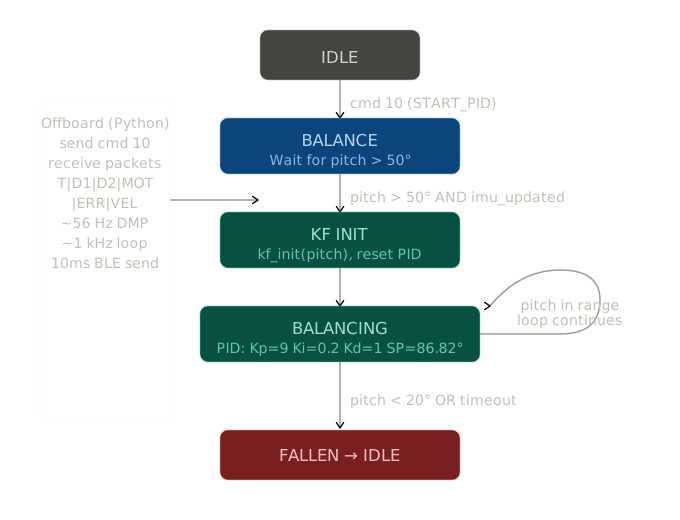
During my lab section, I borrowed his car and tried running the code on it. We decided to try driving the car forward and then go into the inverted pendulum. Immanuel built a simple state machine that would drive the car forward for a set amount of time, try to move backward for another set amount of time, and, if the pitch exceeded a certain threshold, enter balancing mode. I added an extra state to short brake the motors for a brief period of time. However, this did not work super well during the lab section. His car would lift slightly, but didn’t move anywhere near high enough to get into the stunt. To see whether it was a problem with the code or something else, I ported the code to my car (I had to modify the motor functions because they were wired differently). While my car was still unable to fully stand up, it did seem to lift more than Immanuel’s did (about 45 degrees). Going forward, we decided to use my car and just focus on getting it to do the stunt.
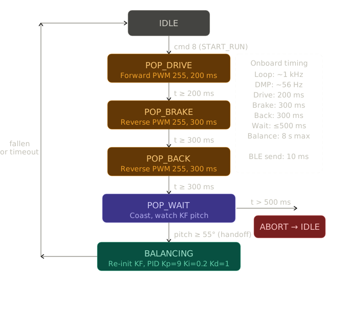
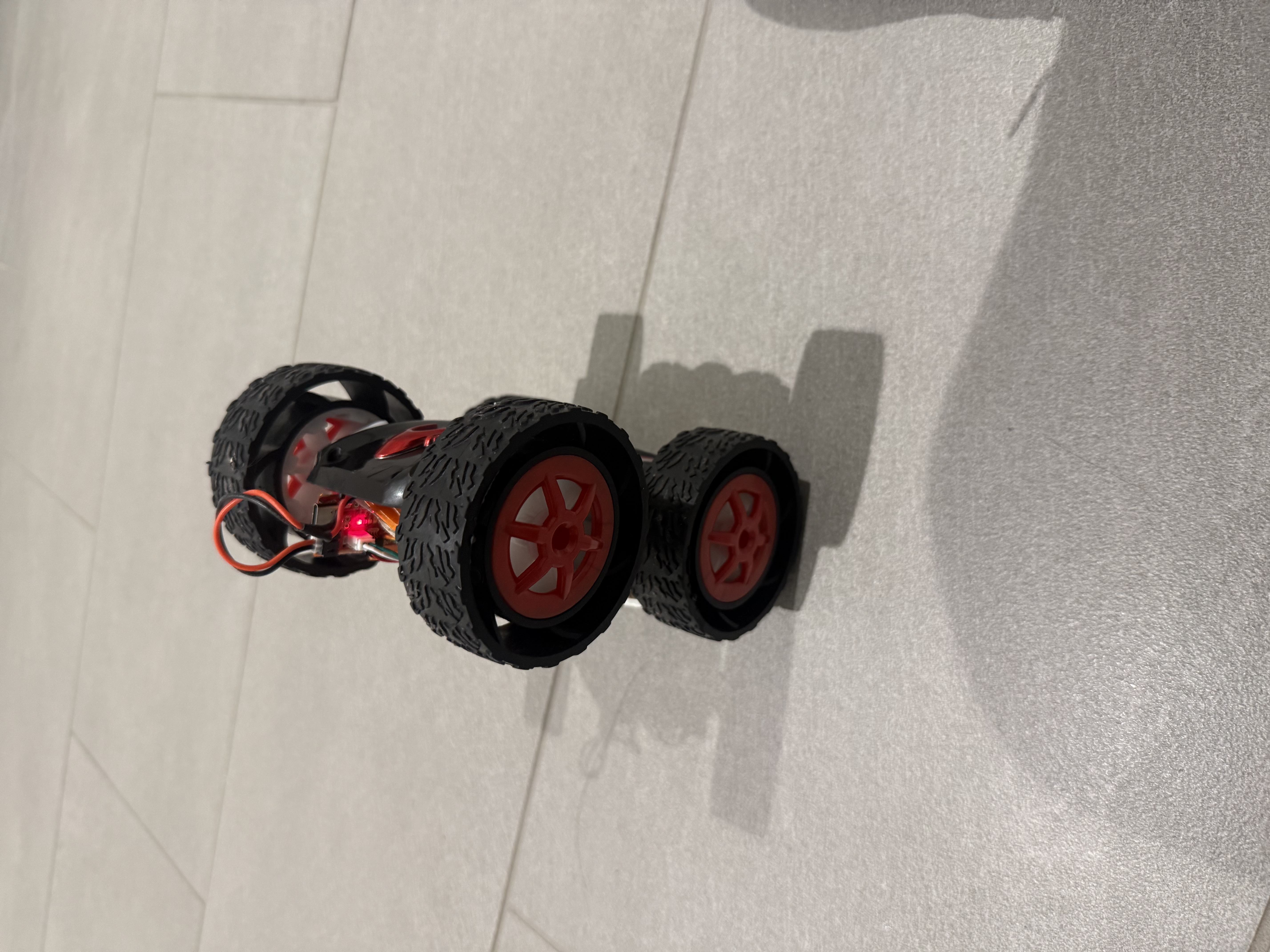
With my car, I remembered that people attached weights to the front when doing the flip stunt (I did the drift). So I tapped a bit of weight to the front of my car. And when I ran it, the car flipped. However, this posed a new problem. I needed to tape the weight to the front of my car to flip it. However, this meant that when the car started to flip, the weight was now at the bottom of the inverted pendulum. As mentioned in the lecture on the inverted pendulum, the weight should be at the top of the pendulum to provide stability. As such, the car could drive forward and begin the pendulum motion, but it was never able to stabilize itself.
With the knowledge of how to get the car to flip, I turned my attention to the balancing itself. I figured that if I could get the car to balance on form from the standing position, then maybe I could put that together with the driving forward to pull off the entire stunt. Immanuel had written the PID controller, but I had to adjust the gains significantly to improve its performance. I played around with it for a few hours on my own, with limited success. I found that I needed a Kp value of at least 10 to get anything decent, but going near 15 would cause the car to oscillate. I added more Kd, but it actually seemed to drag the setpoint down a bit. The car wanted to settle at a tilted angle rather than directly upright. My theory is that the version of the code used the Kalman Filter and DMP to calculate the pitch. However, the DMP is kind of slow, so I don’t think it was providing data fast enough for the Kalman Filter to keep up. To solve this problem, we do have a complimentary filter to look at gyroscope, but this cannot provide absolute pitch, only changes (which is why it is fused with the DMP pitch). At the robot day showcase, we talked with another student who had a pretty stable inverted pendulum (I don’t know his name, though, sorry), and he said that he used the raw gyro values for some of his data because they are much faster. Another bug we ran into was how pitch was calculated. Immanuel had a bug in his code from previous labs that was causing problems around 90 degrees, which is where we wanted our setpoint. He originally fixed it by using asin, but that meant that the pitch would reach 90 degrees and then start falling again. I fixed it by using atan2, so it was +-180 degrees. The car would jump if it flipped over entirely, but as the car flipping meant the pendulum had failed, this was not a bug.
bool read_dmp_pitch() {
    unsigned long now = millis();
    bool got_data = false;

    // ── Raw gyro integration (runs every call for high-rate rate estimate) ──
    if (myICM.dataReady()) {
        myICM.getAGMT();
        float rate = GYRO_AXIS;   // deg/s on selected axis
        float dt_s = (last_imu_time == 0) ? 0.0f
                                          : (float)(now - last_imu_time) / 1000.0f;
        if (dt_s > 0.0f && dt_s < 0.1f)
            gyro_pitch += rate * dt_s;
        last_imu_time = now;
    }

    // ── DMP quaternion
    icm_20948_DMP_data_t data;
    do {
        myICM.readDMPdataFromFIFO(&data);
        if (myICM.status == ICM_20948_Stat_Ok ||
            myICM.status == ICM_20948_Stat_FIFOMoreDataAvail) {
            if ((data.header & DMP_header_bitmap_Quat6) > 0) {
                double q1 = ((double)data.Quat6.Data.Q1) / 1073741824.0;
                double q2 = ((double)data.Quat6.Data.Q2) / 1073741824.0;
                double q3 = ((double)data.Quat6.Data.Q3) / 1073741824.0;
                double q0 = sqrt(max(0.0, 1.0 - q1*q1 - q2*q2 - q3*q3));

                // asin-based pitch
                // double sinp = 2.0 * (q0*q2 - q3*q1);
                // sinp = constrain((double)sinp, -1.0, 1.0);
                // float dmp_pitch = (float)(asin(sinp) * 180.0 / PI);

                double sinp = 2.0 * (q0*q2 - q3*q1);
                double cosp = 1.0 - 2.0 * (q2*q2 + q1*q1);
                float dmp_pitch = (float)(atan2(sinp, cosp) * 180.0 / PI);

                // Complementary filter: gyro short-term, DMP long-term
                current_pitch = 0.98f * gyro_pitch + 0.02f * dmp_pitch;
                gyro_pitch    = current_pitch;   // re-sync gyro integrator

                got_data = true;
            }
        }
    } while (myICM.status == ICM_20948_Stat_FIFOMoreDataAvail);

    return got_data;
}θ̈ = α₁ θ − α₂ u, x = [θ, θ̇]ᵀ
Ad = [[1.0, 0.0177], Bd = [[0.0 ],
[0.0949, 1.0 ]] [-0.7965]]
C = [1, 0]
void build_kf_matrices() {
Ad = {1.0f, KF_DT,
KF_ALPHA1 * KF_DT, 1.0f };
Bd = {0.0f, -KF_ALPHA2 * KF_DT};
C_kf = {1.0f, 0.0f};
Sigma_u = {kf_sigma1*kf_sigma1, 0.0f,
0.0f, kf_sigma2*kf_sigma2};
Sigma_z = {kf_sigma3 * kf_sigma3};
}Immanuel and I met up and started working on tuning the robot together. We had similar results to my solo tuning session. We needed a high Kp, but too high of a Kp would cause oscillations. Adding weights to the front of the car would cause it to flip, but would make the pendulum unstable. We did find that adding a bit of rotation would help the car to stay stable. It would cause the car to run in circles while it balanced, but it could remain stable for around 5 seconds. We used Kp: 9, Ki: 0.2, Kd: 1. One of these runs is shown below.
Overall, the best that we could manage with the PID controller was a few seconds of balancing. It seems like this is in line with other groups’ results. To improve performance, extensive simulations using MATLAB (or another method) are needed. Because we were hand-tuning the parameters, it was hard to get the exact values that we needed. Another method we decided to try was a simple bang-bang controller. We set it up so the robot would run in one direction until it hit a certain pitch, then change direction until it hit the complementary pitch. We had parameters we could change, like the angle, and two zones where it would run at different motor speeds. Despite being a fairly simple controller, we managed to get a few good attempts out of the bang-bang controller. Every once in a while, it would stand up for roughly 3-5 seconds. However, it was not consistent at all. We still think the PID controller is the better choice, but we were pleasantly surprised by the bang-bang controller. Ultimately, we were only able to get the inverted pendulum working from a standing position.
float error = SETPOINT_DEG - pitch_kf;
float dt_s  = (prev_pid_time == 0) ? 0.0f
                                   : (float)(now - prev_pid_time) / 1000.0f;

float p_term = Kp * error;

// Integral — only inside balance window, clamp with anti-windup
if (fabsf(error) <= BALANCE_WINDOW && dt_s > 0.0f) {
    integral += error * dt_s;
    integral  = constrain(integral, -WINDUP_LIMIT, WINDUP_LIMIT);
} else if (fabsf(error) > BALANCE_WINDOW) {
    integral = 0.0f;   // reset outside window
}
float i_term = Ki * integral;

// Derivative on measurement (KF rate is smooth — no extra filter needed)
float d_term = -Kd * pitchrate_kf;

float pid_out = p_term + i_term + d_term;
pid_out = constrain(pid_out, -255.0f, 255.0f);

prev_pid_time = now;
return pid_out;
}
int run_bang_bang_pwm(float pitch_deg, unsigned long now) {
    float err = SETPOINT_DEG - pitch_deg;

    if (fabsf(err) <= BB_ERR_OFF_DEG)
        bb_schmitt = 0;
    else if (err >= BB_ERR_ON_DEG)
        bb_schmitt = 1;
    else if (err <= -BB_ERR_ON_DEG)
        bb_schmitt = -1;

    int out_sign = bb_schmitt;
    if (out_sign != bb_last_out && (now - bb_last_sw) < BB_MIN_SWITCH_MS)
        out_sign = bb_last_out;
    if (out_sign != bb_last_out) bb_last_sw = now;
    bb_last_out = out_sign;

    return out_sign * BB_FIXED_PWM;  // e.g. 120
}
Collaborations
For this lab, I worked extensively with Immanuel Koshy. We worked on tuning the PID controller together. I also referenced previous inverted pendulum stunts, including the work of Stephan Wagner, Nita Kattimani, Aravind Ramaswami, and Anunth Ramaswami. AI was used to format the lab report in Markdown.