Lab 2: IMU
Objective
The objective of this lab was to learn how to work with the Inertial Measurement Unit (IMU). We are using the ICM-20948 over I²C, which allows us to use the Qwiic connector on the Artemis to communicate with the IMU using only one wire. We were also given our cars this week, and had to record a stunt with them to learn how the car works, mostly with the battery.
Lab Work
IMU Library
To start the lab, we had to install the IMU library on in the Arduino IDE. I strongly dislike the Arduino IDE, so I decided to move to PlatformIO. PlatformIO is a program used for embedded development. It supports many different boards and frameworks, including Arduino. One of the really nice features of PlatformIO is the platformio.ini file. Using this file, I can specify the board, framework, and libraries I am using.
platformio.ini file (click to expand)
[env:regular]
platform = https://github.com/nigelb/platform-apollo3blue.git
board = SparkFun_RedBoard_Artemis_Nano
framework = arduino
platform_packages =
    framework-arduinoapollo3 @ https://github.com/sparkfun/Arduino_Apollo3.git
lib_deps =
	sparkfun/SparkFun 9DoF IMU Breakout - ICM 20948 - Arduino Library@^1.3.2
	arduino-libraries/ArduinoBLE@^1.5.0
monitor_speed = 115200
I used the Arduino IDE to run the example sketch for the IMU to play with the AD0_VAL pin. This pin sets the address on the I²C bus for the IMU. The default value is 1, and if changed to 0 the Artemis won’t find the IMU. The user could bridge two pads on the back of the IMU board if they wanted to change the address. The two I²C addresses are 0x68 and 0x69 in hex.
After verifying that the IMU could connect, I started playing with the IMU. I printed all the accelerometer, gyroscope, and magnetometer data over serial, and used SerialMonitor to plot it. An example output is shown in Figure 1. The data is clearly quite noisy. I did notice that one of the values on the accelerometer was always around 10,000 mg’s. This value would shift depending on which orientation I held the IMU. The gyroscope would react to movement, but would settle down to basically 0 if I didn’t touch it.

Accelerometer
The next part of the lab was focused on the accelerometer. I first had to calculate the pitch and roll of the IMU using the accelerometer. After calculating the pitch and roll, I printed them over serial and printed the output of moving it 90 degrees on each axis, shown in Figure 2. Looking at the figure, you can see the 90 degree rotations. But the axis which isn’t moving is very noisy. I think this is from my hands shaking while I rotate the board, the vibrations calmed down if I held the IMU at the bottom of the board.
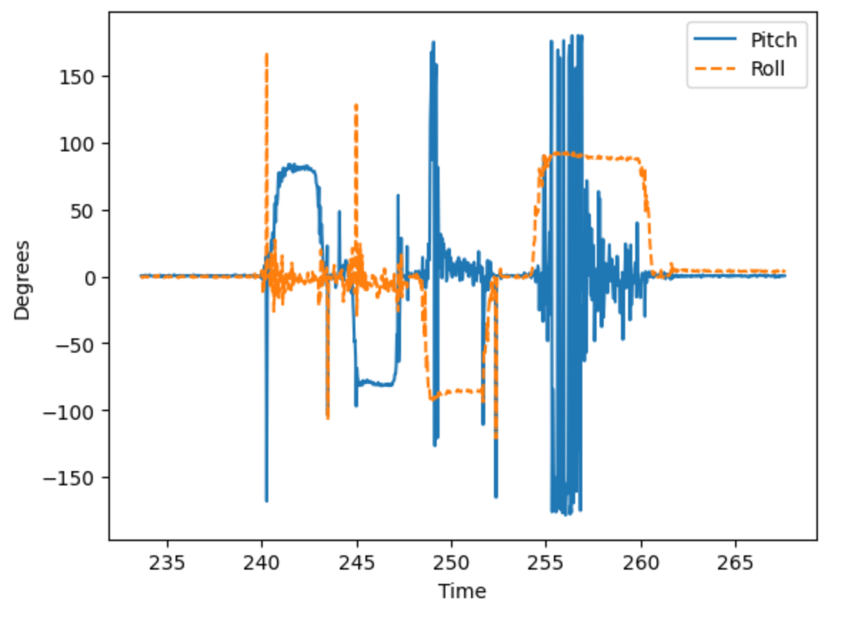
Pitch and Roll with Accelerometer (click to expand)
inline float calculatePitch(ICM_20948_I2C *sensor) {
    return atan2(sensor->accX(), sensor->accZ()) * 57.295779513f; // pitch (in deg)
}

inline float calculateRoll(ICM_20948_I2C *sensor) {
    return atan2(sensor->accY(), sensor->accZ()) * 57.295779513f; // roll (in deg)
}
FFT
After plotting the accelerometer data in the time domain, I also plotted the data in the frequency domain using an FFT. Figure 3 shows the FFT of Figure 2. As shown, most of the noise and accelerations are pretty low frequency, with a large frequency around 0. I think that this large spike is caused by me rotating the board.
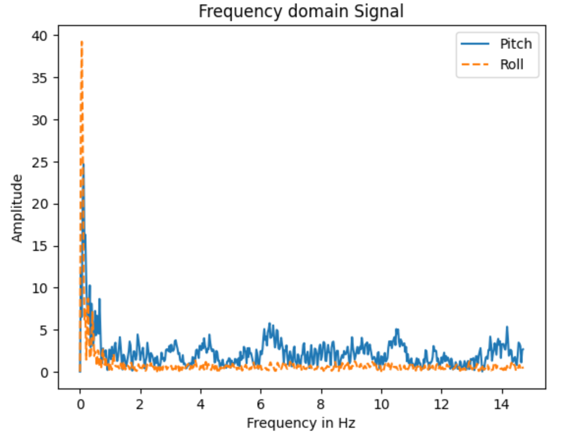
With this data, I could figure out what cutoff frequency to use for a low pass filter, and the associated alpha value. A low pass filter is used to filter out some of the noise and frequencies that I don’t want the IMU to read. The alpha value is used to weight the low pass filter, and is determined by the cutoff frequency.
Low pass filter equation:
Alpha calculations:
Note that T is the sample time, so it depends on the execution time of the loop, so alpha could change depending on the program. I started with a cutoff frequency of 15 Hz, because I wanted to make sure that my filter was effective, but would sill be responsive.
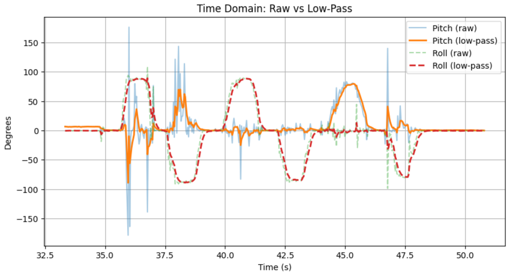
I tested the filter, and compared the raw data to the filtered data, which can be seen in Figure 4. The LPF seems to be working, as the filtered response is generally much smoother than the raw data. There is still some bumps on the graph, but mostly when I am moving the IMU myself.
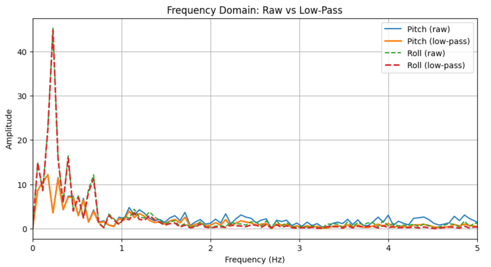
I also took the FFT of both the LPF and raw data to compare them, shown in Figure 5. There is still a large spike close to 0 Hz, but the filtered lines generally have less amplitude across the frequency spectrum.
Accelerometer Low Pass Filter Code (click to expand)
typedef struct LowPass {
    float value_n;
    float value_n_1;
    float alpha;
} LowPass;

void updateLowPass(LowPass *filter, float new_value) {
    filter->value_n = filter->alpha * new_value + (1 - filter->alpha) * filter->value_n_1;
    filter->value_n_1 = filter->value_n;
}
Gyroscope
With the accelerometer filtered, it was time to look at the gyroscope. The gyroscope measures rate of change, so in order to estimate the pitch and roll, we start with an initial value (assumed to be 0 in this case) and integrate the values.
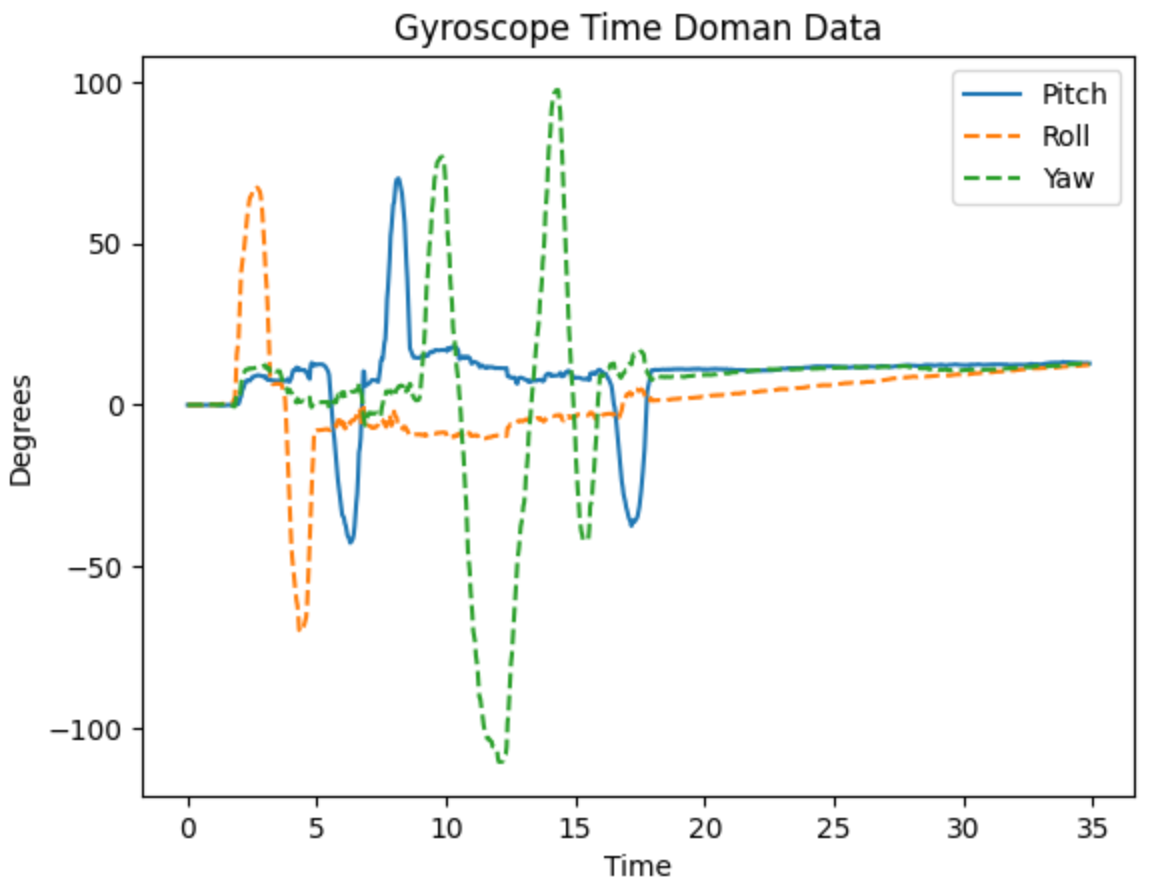
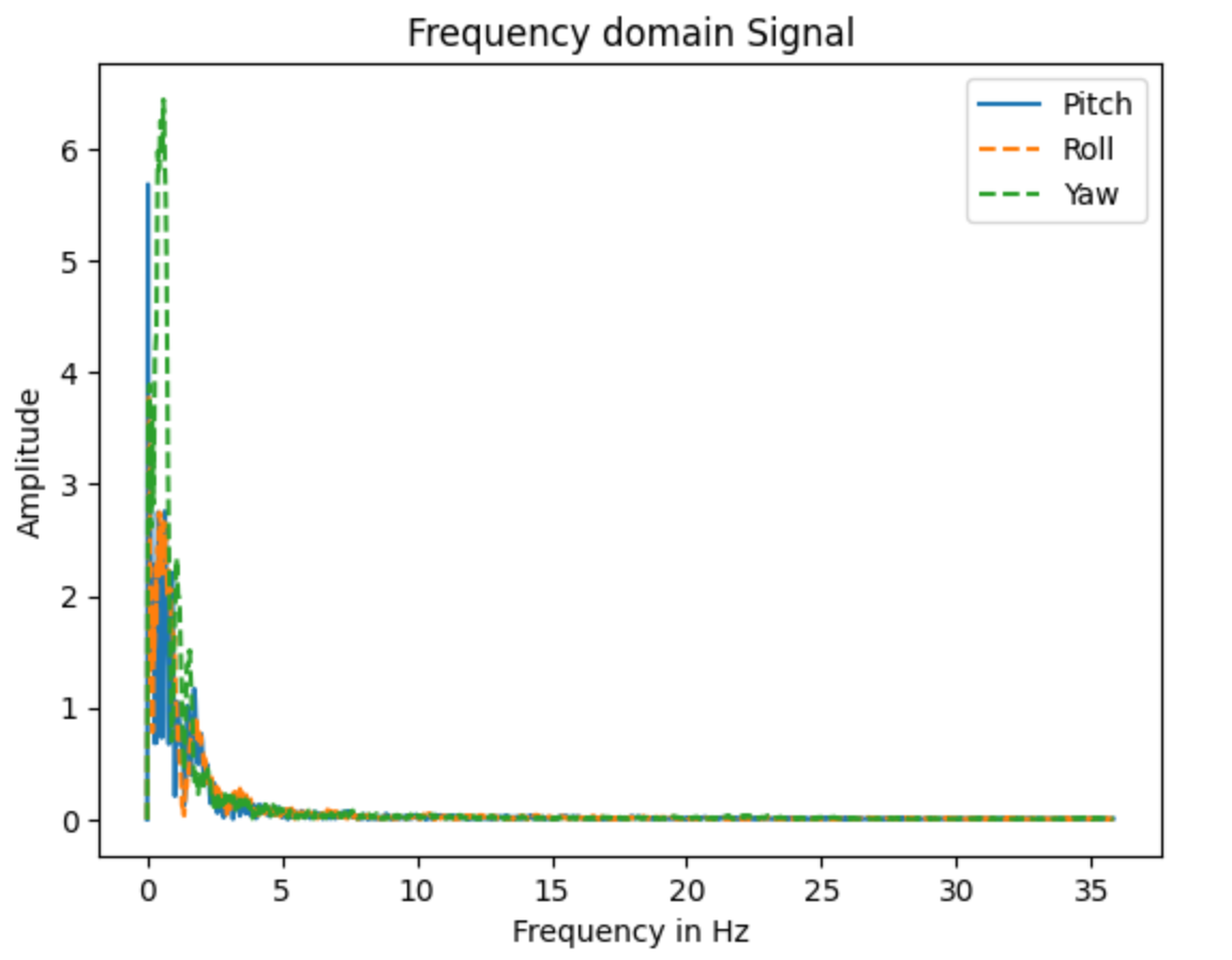
This has the advantage of being able to calculate the yaw, which isn’t possible with the accelerometer. The downside to this integration approach is that error grows over time, so the sensor will drit and become unreliable. The advantage is that the gyro isn’t very noisy. I plotted the gyro angle estimations, as well as the FFT, shown in Figures 6 and 7. In Figure 7, we can see that other than the spikes around 0 Hz, the noise on the gyroscope is significantly lower than the accelerometer.
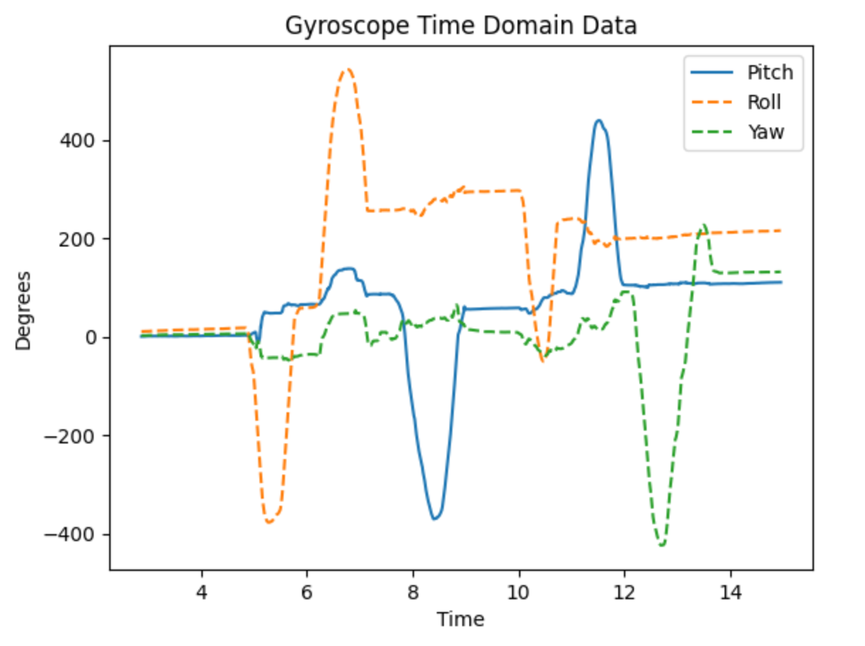
I also tried removing the loop delay to increase the sampling rate, which is shown in Figure 8. I think that it makes it more sensitive, but also increases the error because the error is being added more frequently.
Gyroscope Pitch, Roll, and Yaw Code (click to expand)
typedef struct Attitude {
    float pitch;
    float roll;
    float yaw;
} Attitude;

void updateGyroAttitude(Attitude *attitude, ICM_20948_I2C &sensor, const float dt) {
    attitude->pitch += sensor.gyrY() * dt; // Integrate gyro Y to get pitch (deg)
    attitude->roll += sensor.gyrX() * dt;  // Integrate gyro X to get roll (deg)
    attitude->yaw += sensor.gyrZ() * dt;   // Integrate gyro Z to get yaw (deg)
    // Wrap yaw to 0-360

    if (attitude->yaw >= 360.0f) {
      attitude->yaw -= 360.0f;
    } else if (attitude->yaw < 0.0f) {
      attitude->yaw += 360.0f;
    }
}
Complementary Filter
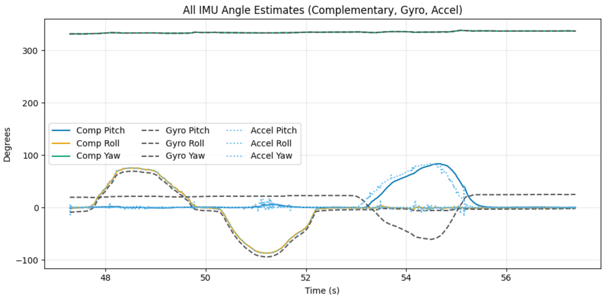
The complementary filter is a way to combine the data from both sensors to make a more accurate prediction. The goal of a complementary filter is to trust the gyroscope over very short timescales because it has lower noise, but over longer timescales trust the accelerometer because it is more accurate. The equation for a complementary filter is as follows:
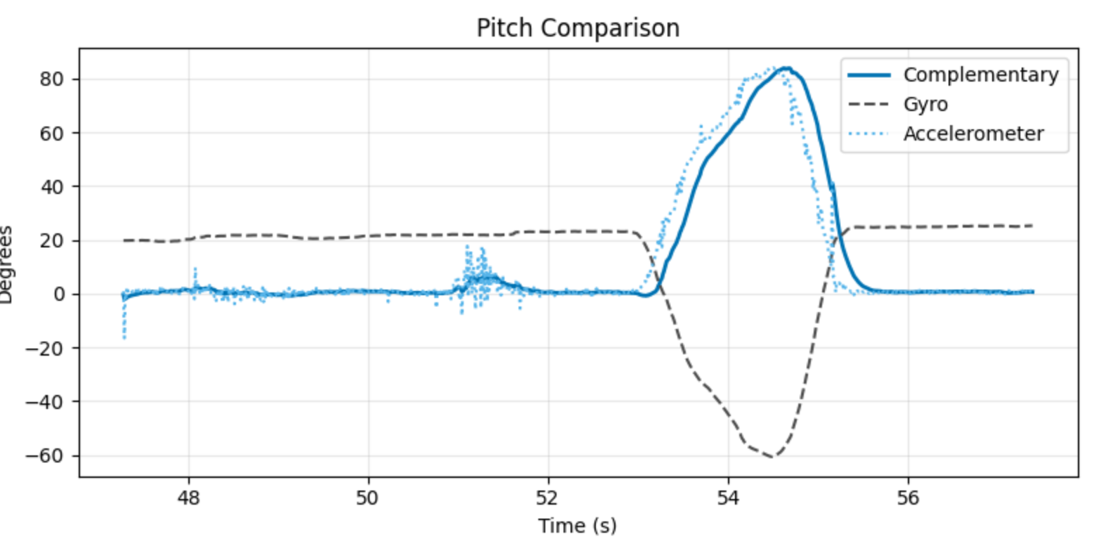
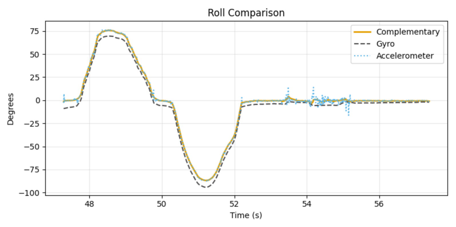
where is the angle from the gyroscope, is from the accelerometer, and is used to weight both. A low theta will trust the gyro in the short term, and the accelerometer in the longer term, which is the behavior that we expect. I printed from the complementary filter, accelerometer, and gyroscope to compare them. Figure 9 shows the pitch, roll, and yaw for the complementary filter, gyroscope, and LPF accelerometer. Figure 10 shows only the pitch for all three, and Figure 11 shows the roll. In all three figures, the complementary filter is cleaner than the accelerometer or gyroscope individually, showing that it is working.
Complementary Filter Code (click to expand)
typedef struct CompFilter {
    Attitude comp_attitude;
    float alpha;
    float dt;
} CompFilter;

void updateCompFilter(CompFilter *filter, ICM_20948_I2C &sensor, const Attitude& accel_attitude) {
  filter->comp_attitude.pitch = (filter->comp_attitude.pitch + sensor.gyrY() * filter->dt) * (1 - filter->alpha) + accel_attitude.pitch * filter->alpha;
  filter->comp_attitude.roll = (filter->comp_attitude.roll + sensor.gyrX() * filter->dt) * (1 - filter->alpha) + accel_attitude.roll * filter->alpha;
  filter->comp_attitude.yaw += sensor.gyrZ() * filter->dt; // Yaw is only from gyro

  // Wrap yaw to 0-360
  if (filter->comp_attitude.yaw >= 360.0f) {
    filter->comp_attitude.yaw -= 360.0f;
  } else if (filter->comp_attitude.yaw < 0.0f) {
    filter->comp_attitude.yaw += 360.0f;
  }
}
Data Rate
The IMU updates at a fixed frequency, so I wanted to determine whether the loop could ever run without receiving new data. I configured the LED to turn on when new data was available and off otherwise. If multiple loops occurred without new data, the LED would blink. I tested this in both a minimal IMU-only version and with Bluetooth enabled, and in both cases the LED stayed solid. To both the human eye and a 240 FPS camera, it appeared continuously on.
I also needed to capture IMU data and transmit large amounts over Bluetooth, similar to Lab 1. I chose to store the data using custom structs. The Attitude struct stores pitch, roll, and yaw as floats. The IMUData struct stores an array of Attitude and an index for updating it. I created a single IMUData instance to store complementary filter outputs. This structure keeps the data organized and does not meaningfully increase memory usage.
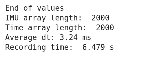
The larger concern is the use of floats. Each float is 32 bits, so an Attitude is 96 bits. With an array size of 2000 samples to capture 6.47 seconds of data, this requires about 24 KB just for the complementary filter output. The compiler reports 22.3% RAM usage. Much of this precision is likely unnecessary, since attitude values are bounded within ±90°. Switching to 16-bit integers would halve the memory requirement, but would restrict values to integers. A more efficient option would be a 16-bit fixed-point representation, where some least significant bits encode fractional values. This would require a custom implementation, which is why I did not use it here. If RAM becomes constrained, this would be a way to reduce usage.
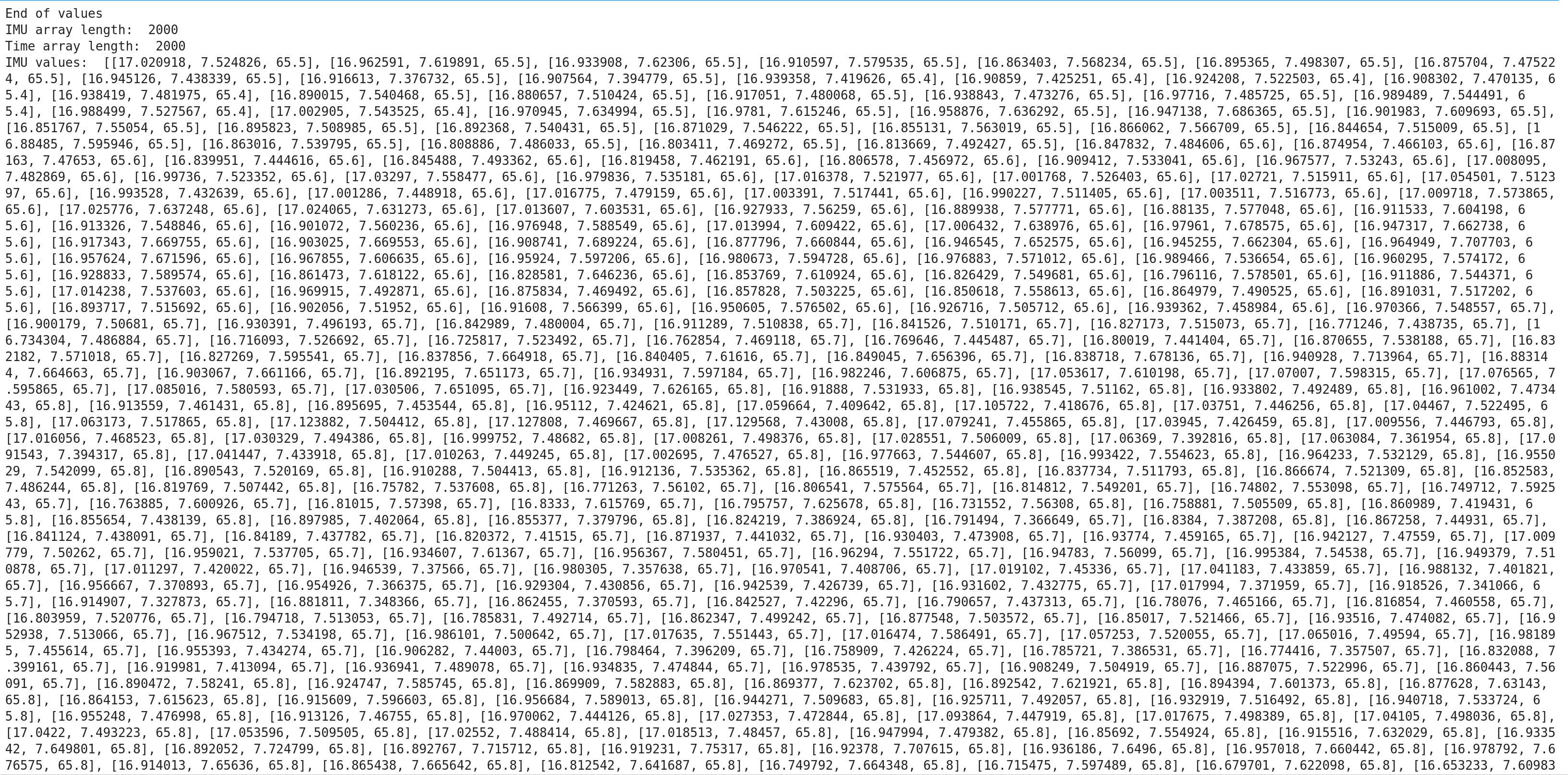
With my array in place, I reused and adapted my code from Lab 1 to transmit all the data over Bluetooth, shown in Figures 11 and 12. Figure 11 shows a clean print, while Figure 12 shows some of the data.
Storing IMU Data Code (click to expand)
struct IMUData {
    Attitude values[DATA_ARR_SIZE];
    int index;
};

void collectIMUData(IMUData &imu_values){
    imu_values.values[imu_values.index] = comp_filter.comp_attitude;
    imu_values.index = (imu_values.index + 1) % DATA_ARR_SIZE;
}
Transmit IMU Data Code (click to expand)
static bool handle_get_imu_readings() {
    Serial.println("Sending IMU readings");

    EString temp_string = EString();
    int tx_result = -1;


    recording = false; // Pause recording while transmitting
    int start = imu_data.index;
    for(int k = 0; k < DATA_ARR_SIZE; k++){
        int i = (start + k) % DATA_ARR_SIZE; // chronological order

        char value_str[30];
        snprintf(value_str, sizeof(value_str), "%lu:%.3f:%.3f:%.3f", time_data.values[i], imu_data.values[i].pitch, imu_data.values[i].roll, imu_data.values[i].yaw);

        // Check if adding this value would exceed MAX_MSG_SIZE
        // Account for comma separator and null terminator
        int needed_len = strlen(value_str) + (temp_string.get_length() > 0 ? 1 : 0);

        if (temp_string.get_length() + needed_len >= MAX_MSG_SIZE - 1) {
            // Send current packet before it overflows
            tx_result = tx_characteristic_string.writeValue(temp_string.c_str());
            Serial.print("Sent packet: ");
            Serial.println(temp_string.c_str());

            // Small delay to allow BLE stack to process
            delay(10);

            // Reset for next packet
            temp_string.clear();
        }

        // Add comma if not first item in current packet
        if (temp_string.get_length() > 0) {
            temp_string.append(",");
        }
        temp_string.append(value_str);
    }

    // Send any remaining data
    if (temp_string.get_length() > 0) {
        tx_result = tx_characteristic_string.writeValue(temp_string.c_str());
        Serial.print("Sent packet: ");
        Serial.println(temp_string.c_str());
        delay(10);
    }

    // Send end marker
    tx_result = tx_characteristic_string.writeValue("end");
    Serial.print("Serial Transmission Result: ");
    Serial.println(tx_result);
    Serial.println("Finished sending array");

    recording = true; // Resume recording after transmit
    return true;
}
Receiving IMU Data Code (click to expand)
done = threading.Event()
time_values = []
imu_values = []

def imu_array_notification_callback(uuid, data: bytearray):
    msg = ble.bytearray_to_string(data).strip()
    #print("Msg received:", repr(msg))

    parts = [p.strip() for p in msg.split(",") if p.strip()]
    for token in parts:
        if token.lower() == "end":
            print("End of values")
            done.set()
            return

        try:
            time_str, pitch_str, roll_str, yaw_str = token.split(":", 3)
            imu_values.append([float(pitch_str), float(roll_str), float(yaw_str)])
            time_values.append(int(time_str))
        except ValueError:
            print("Bad token:", repr(token))

def get_imu_data(timeout_s=40.0):
    time_values.clear()
    imu_values.clear()
    done.clear()

    # send command (NO await)
    ble.send_command(CMD.GET_IMU_READINGS, "")

    t0 = time.time()
    while not done.is_set() and (time.time() - t0) < timeout_s:
        ble.sleep(0.01)

    if not done.is_set():
        print("Timeout reached.")
    return list(imu_values), list(time_values)


# start notify
try:
    connectBLE(ble)

    ble.start_notify(ble.uuid['RX_STRING'], imu_array_notification_callback)
except Exception as e:
    if "Notify acquired" in str(e):
        print("Notify already active; continuing.")
    else:
        raise
time.sleep(0.2)

imu_vals, time_vals = get_imu_data()

print("IMU array length: ", len(imu_values))
print("Time array length: ", len(time_values))
#print("IMU values: ",imu_vals)
#print("Time values:", time_vals)

t = np.array(time_vals, dtype=np.int64)

# if time_vals are in milliseconds:
dt = np.diff(t)              # dt in ms
ave_dt = dt.mean()           # average dt in ms
sample_rate_hz = 1000.0 / ave_dt
recording_time = (time_vals[-1] - time_vals[0]) / 1000 # Convert from ms to s

print(f"Average dt: {ave_dt:.2f} ms")
print("Recording time: ", recording_time, "s")

try:
    ble.stop_notify(ble.uuid['RX_STRING'])
except Exception as e:
    print("Failed to stop notifications with exception: ", e)
Stunts
As part of the lab, to familiarize ourselves with the RC car, we had to record a stunt. I filmed a pretty basic stunt, just going forwards and spinning out. This stunt is pretty basic, but part of that is because my apartment doesn’t have a ton of room for complex stunts. I found that the car was somewhat hard to control, at least with the remote. It rotated very quickly, which made lining it up on my hallway was difficult. it turned pretty quickly while driving.
Another reason that I filmed such a basic stunt is because I was having troubles with the basic connection to my car. It would sometimes stop responding, or register inputs that I didn’t do. I know that we weren’t meant to film any aerial stunts, but this one happened totally by accident (I was just holding the forward button), so I’m going to share it anyways. (You can hear my frustration at the end when I am pressing buttons but the car isn’t responding).
References
I didn’t work with anyone on this lab, and I didn’t reference any old lab manuals. I did use some AI to help me plot the values in Python.