Lab 4: Motor Drivers
Objective
The objective of this lab was to connect the DRV8833 motor drivers to the motor and integrate the car. After wiring the motor drivers, we then had to show that we could control the car using open loop control.
Lab work
Prelab
For the prelab, we had to think about how we were going to connect the motor drivers. This included determining which pins on the Artemis could be used for PWM control, and wire lengths. We also had to determine how to wire the motor driver outputs in parallel to get more current. All of these will be discussed more in depth later.
Wiring Motor Drivers to Artemis
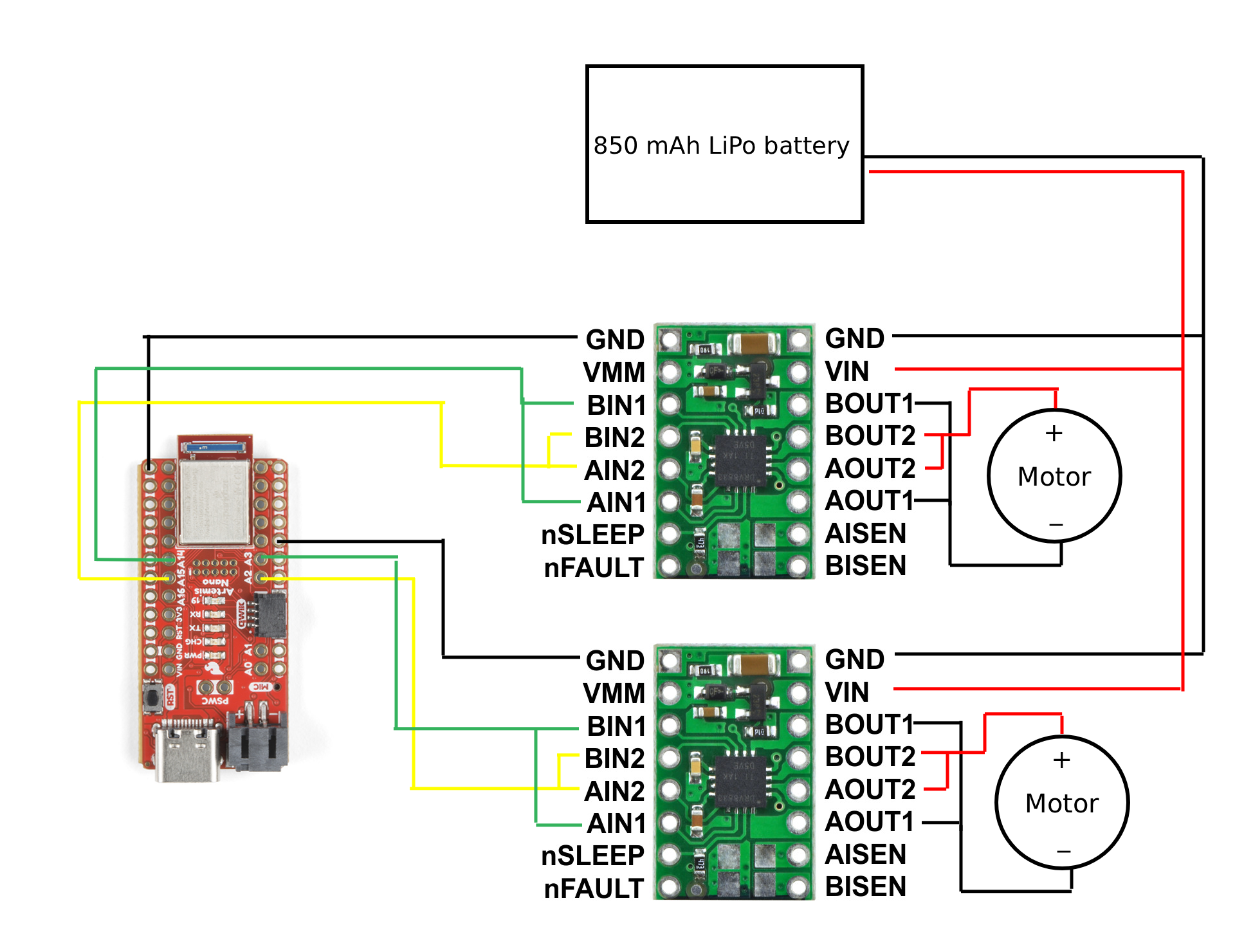
The first step of the lab was to get a single motor driver wired up without a motor connected, and show that we could generate the PWM signals. I decided to wire both motor drivers up at the same time, since I was already at the soldering station. I used pins A2, A3, A14, and A15, although any pin labeled “A” would work with PWM. With the inputs connected, I wrote a basic piece of code to drive each input at a different duty cycle so I could verify that all four were working. I decided to write PWM signals in increments of 50 (the default PWM signal goes from 0-255). The PWM signals can be seen in Figures 1-4.
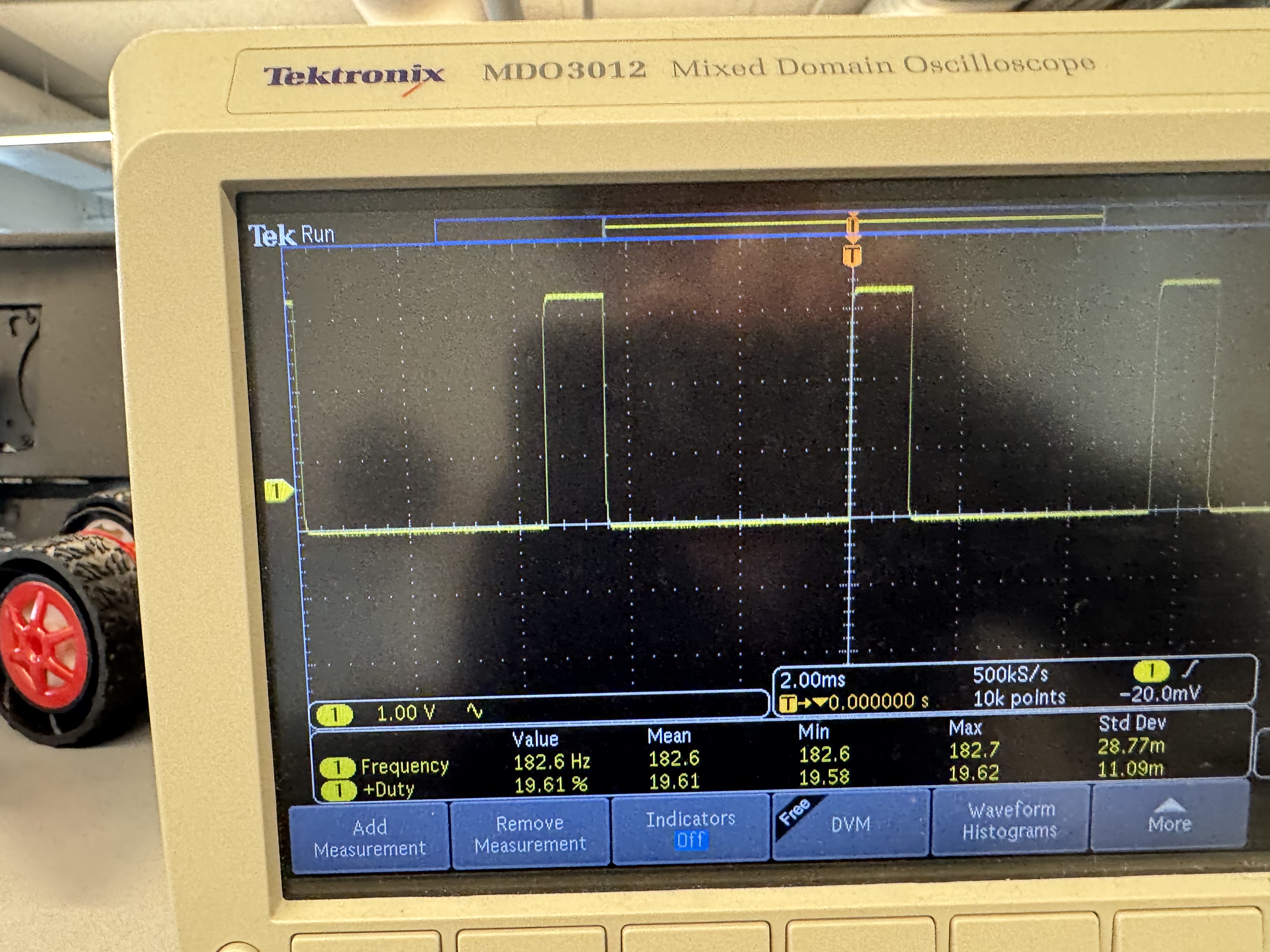
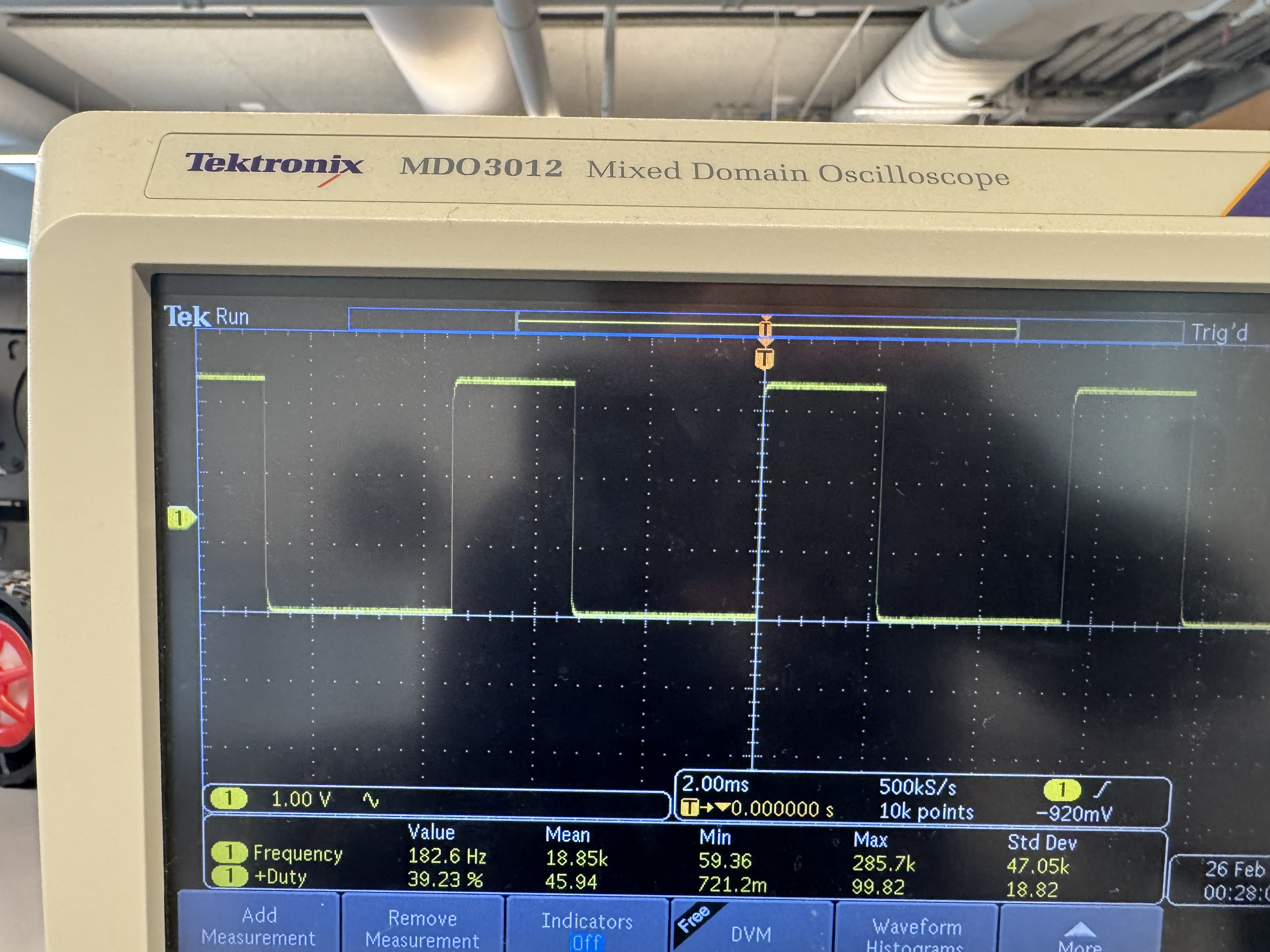
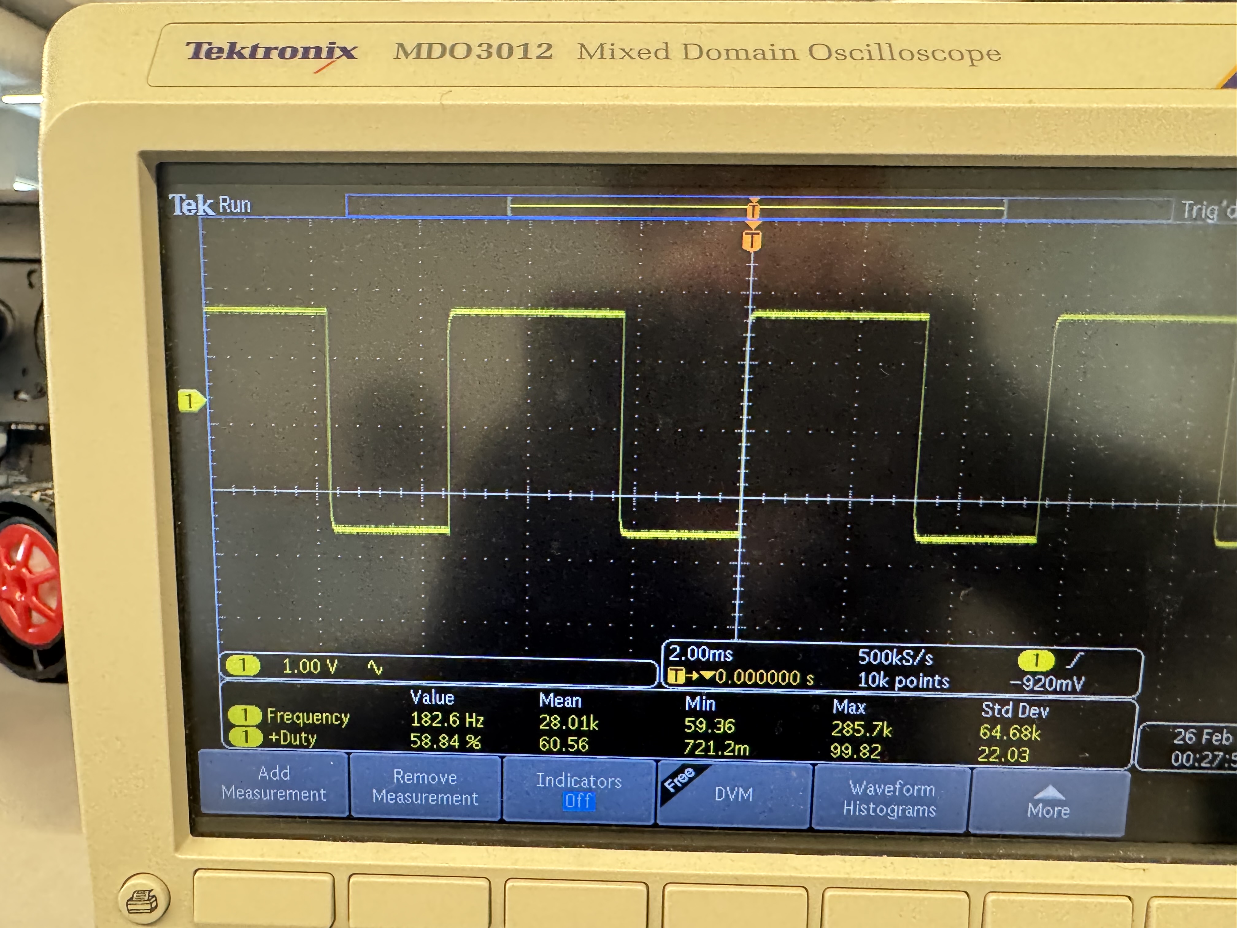
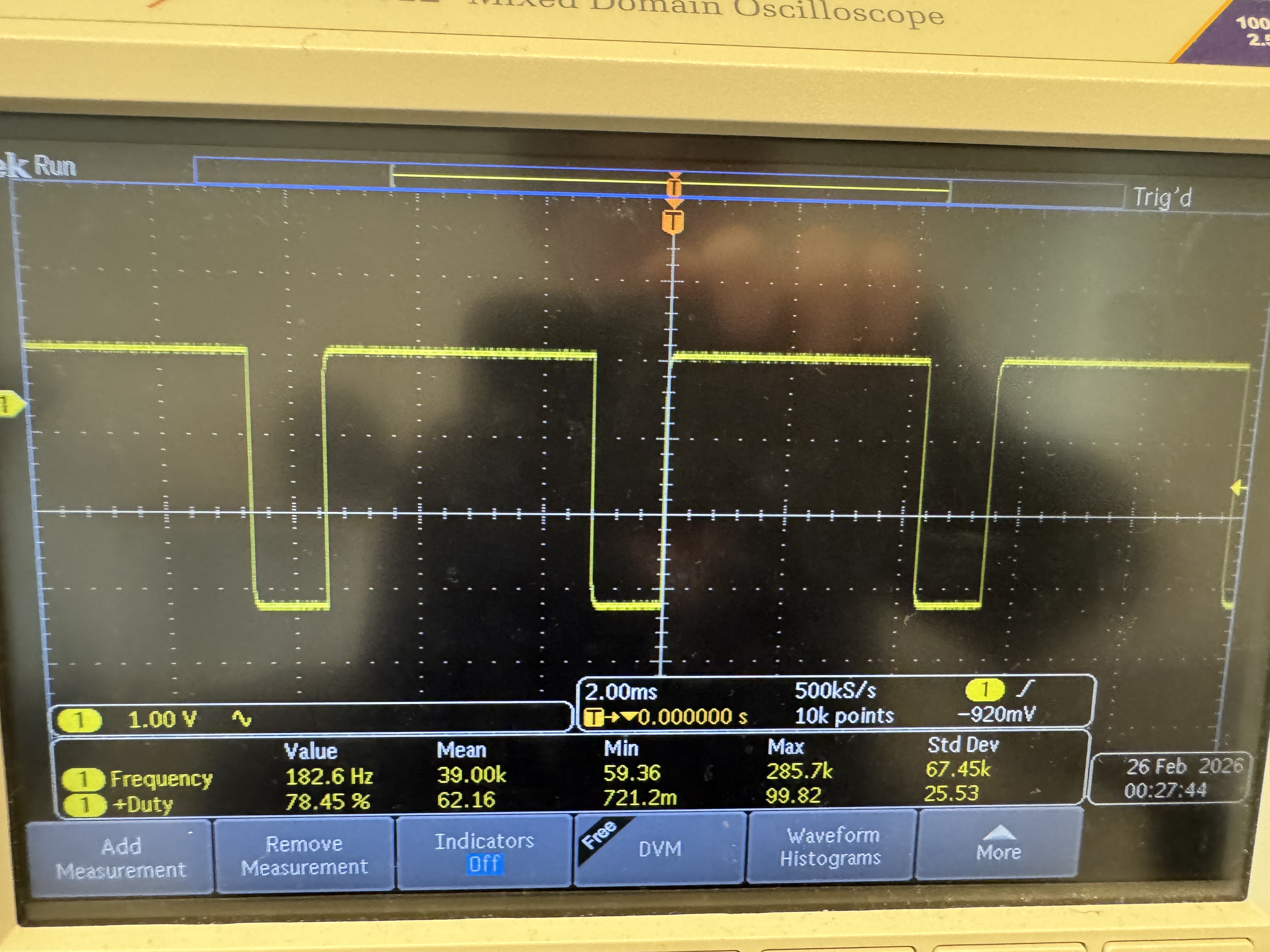
analogWrite(L1, 50); // ~19% duty cycle

analogWrite(L2, 100); // ~39%

analogWrite(R1, 150); // ~59%

analogWrite(R2, 200); // ~78%
Wiring motors to the drivers
Now that I knew that my PWM signals were working, I had to solder the motors to the motor drivers. I connected the AOUT1 and BOUT1 pins, and the AOUT2 and BOUT2 pins on each driver together. This allows me to get more current out of the motor drivers. The motor wiring diagram is shown in Figure 5.
Testing a single motor
After I had wired the motors to the motor drivers, I was ready to test a single motor. I connected one of them to one of the benchtop power supplies, and set the voltage to 3.7V, the same voltage as the 850mAh battery used later. I set the current to around 3A, which the motor shouldn’t draw, but I had to make sure it wasn’t current limited. I then sent a PWM command to the motor. This test is shown in Figure 6. I implemented a function where I input a percentage of max PWM value and a polarity (+-100%) which sets the direction to make future programming easier.
typedef enum channel{
    RIGHT,
    LEFT
} Channel;

// Percent from -100 to 100 to set direction as well
inline bool setMotor(channel chan, float percent){

    if (percent > 100 || percent < -100) return false;
    if (percent == 100) percent = 99; //Making sure to always have a bit of duty cycle
    if (percent == -100) percent = -99;

    if (chan == LEFT) percent = -percent;   // Inverting one motor to keep direction the same

    bool forward = true;
    if(percent < 0) forward = false;

    int val = (int)((abs(percent) / 100.0) * 255);
    Serial.printf("Val: %d\n", val);

    int pin1, pin2;

    if (chan == RIGHT) {
        pin1 = R1; pin2 = R2;
    } else {
        pin1 = L1; pin2 = L2;
    }

    if (forward) {
        analogWrite(pin1, val);
        analogWrite(pin2, 0);
    } else {
        analogWrite(pin1, 0);
        analogWrite(pin2, val);
    }

    return true;
}void loop(){
if(millis() - prev_time > 3000){
if (mode==false) {
Serial.println("Timer triggered!");
motor_speed = -motor_speed;
setMotor(RIGHT, motor_speed);
mode = true;
}
prev_time = millis();
}
}Testing both motors
After I had independently tested each motor, I was ready to test both motors on the battery. I modified the code so that it would run the motors for 3 seconds, stop them for 3 seconds, and then run them again. I tested this on the floor, and the result of this test is shown in Figure 7.
motor_speed = 50

void loop(){
  if(millis() - prev_time > 3000){
    if (mode==false) {
      Serial.println("Timer triggered!");
      motor_speed = -motor_speed;
      setBothMotors(motor_speed, motor_speed);
      mode = true;
    } else {
      stopBothMotors();
      mode = false;
    }
    prev_time = millis();
  }

}
Installing all components in the car
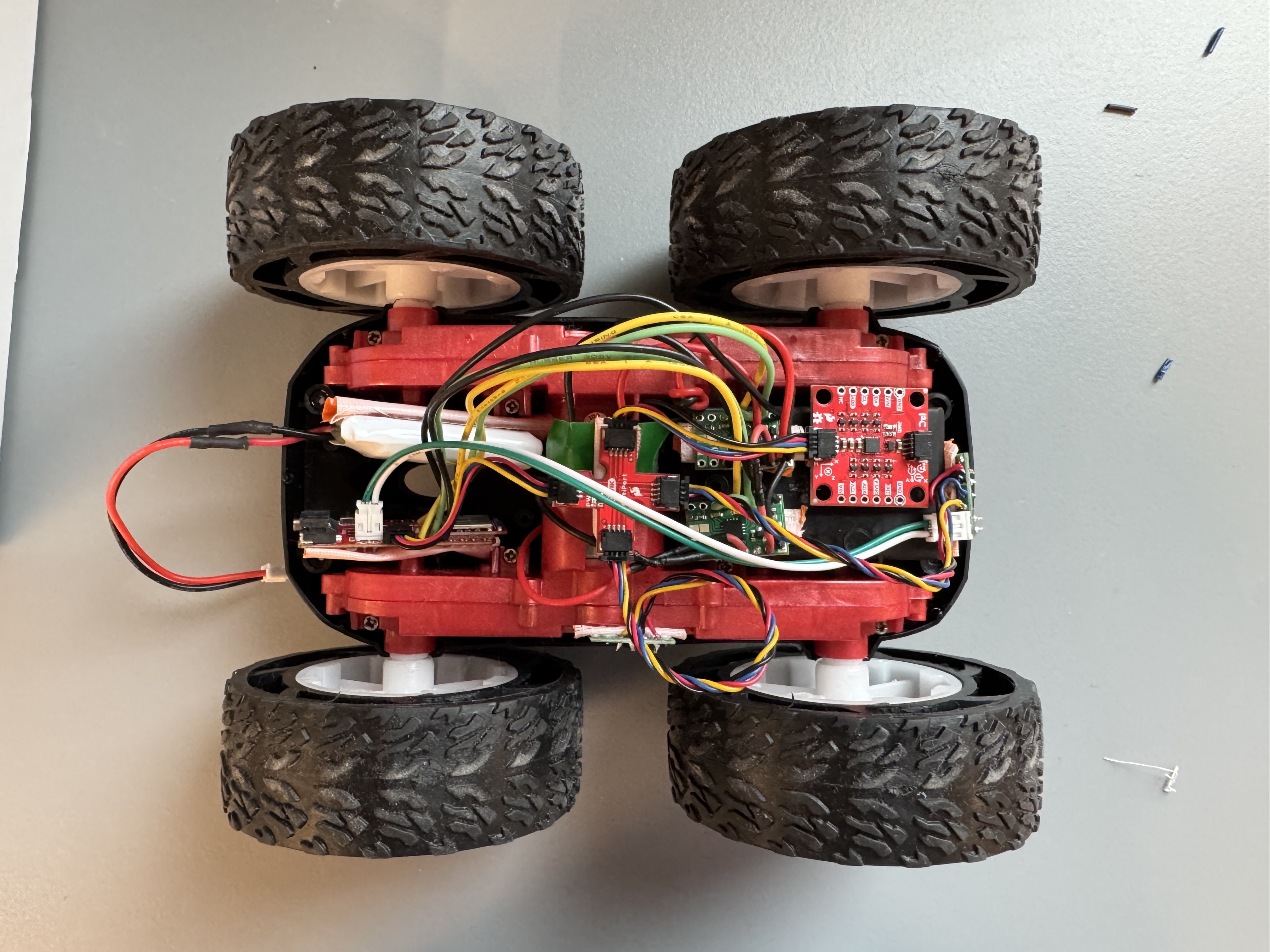
With the basics of driving working, I was ready to mount everything in the car. I just used duct tape, and rolled it to make it double sided to mount all the components. I’m might change this later, because some of my components still move around when mounted using this method, and the 750mAh battery and microcontroller don’t mount super well using this method. Figure 8 shows all the components mounted. I decided to put one ToF sensor in the front of the car, and another on the right side so I could follow walls using it if I wanted to. (I also still have a bit of cable managment to do).
Lowest PWM Value
One of the things that I needed to test for this lab is what the lowest PWM value to start the car is. In order to start moving, the motors first need to overcome static friction both inside the motors and on the wheels/floor. This requires a higher PWM value than is required to keep the car moving. To test the lowest value, I started with a small percentage of the max PWM, and increased until I saw the car actually move. I found that I needed to set the wheels to 40% to get them to spin, which corresponds to a PWM value of 102.
Calibration
One of the problems with the car is that the motors do not spin at the same speed, even when set to the same PWM value. To solve this problem, I had to implement a calibration factor on the car. But first, I implemented a basic way to control the motors using Bluetooth. I added a SET_MOTOR_JOB command and implemented a basic way to run the motors for a set amount of time.
struct MotorJob {
  bool active = false;
  uint32_t stop_at_ms = 0;
  int left_percent = 0;
  int right_percent = 0;
};

void startMotorJob(int right_percent, int left_percent, uint32_t duration_ms);

void serviceMotorJob();
static MotorJob motor_job;

void startMotorJob(int right_percent, int left_percent, uint32_t duration_ms){
    motor_job.active = true;
    motor_job.right_percent = right_percent;
    motor_job.left_percent = left_percent;
    motor_job.stop_at_ms = millis() + duration_ms;
    setBothMotors(right_percent, left_percent);
}

void serviceMotorJob(){
    if (!motor_job.active) return;
  // wrap-safe compare
  if ((int32_t)(millis() - motor_job.stop_at_ms) >= 0) {
    motor_job.active = false;
    stopBothMotors();
  }
}static bool handle_set_motor_job() {
float right_percent, left_percent;
int duration_ms_i;
bool success;
char char_arr[MAX_MSG_SIZE];
// Extract first float from command string
success = robot_cmd.get_next_value(left_percent);
if (!success)
return false;
// Extract second float from command string
success = robot_cmd.get_next_value(right_percent);
if (!success)
return false;
// Extract third float from command string
success = robot_cmd.get_next_value(duration_ms_i);
if (!success)
return false;
if (duration_ms_i < 0) duration_ms_i = 0; // bounds checking just in case
uint32_t duration_ms = (uint32_t)duration_ms_i;
DEBUG_PRINTF("Left percent: %f Right percent: %f duration (ms): %d\n", left_percent, right_percent, duration_ms);
snprintf(char_arr, MAX_MSG_SIZE, "l:%f,r:%f,d:%d", left_percent, right_percent, duration_ms);
EString temp_string = EString();
temp_string.clear();
temp_string.append("Robot received: ");
temp_string.append(char_arr);
tx_estring_value.clear();
tx_estring_value.append(temp_string.c_str());
tx_characteristic_string.writeValue(tx_estring_value.c_str());
startMotorJob(right_percent, left_percent, duration_ms); // Start after the bluetooth return msg so that doesnt interfere# left right duration
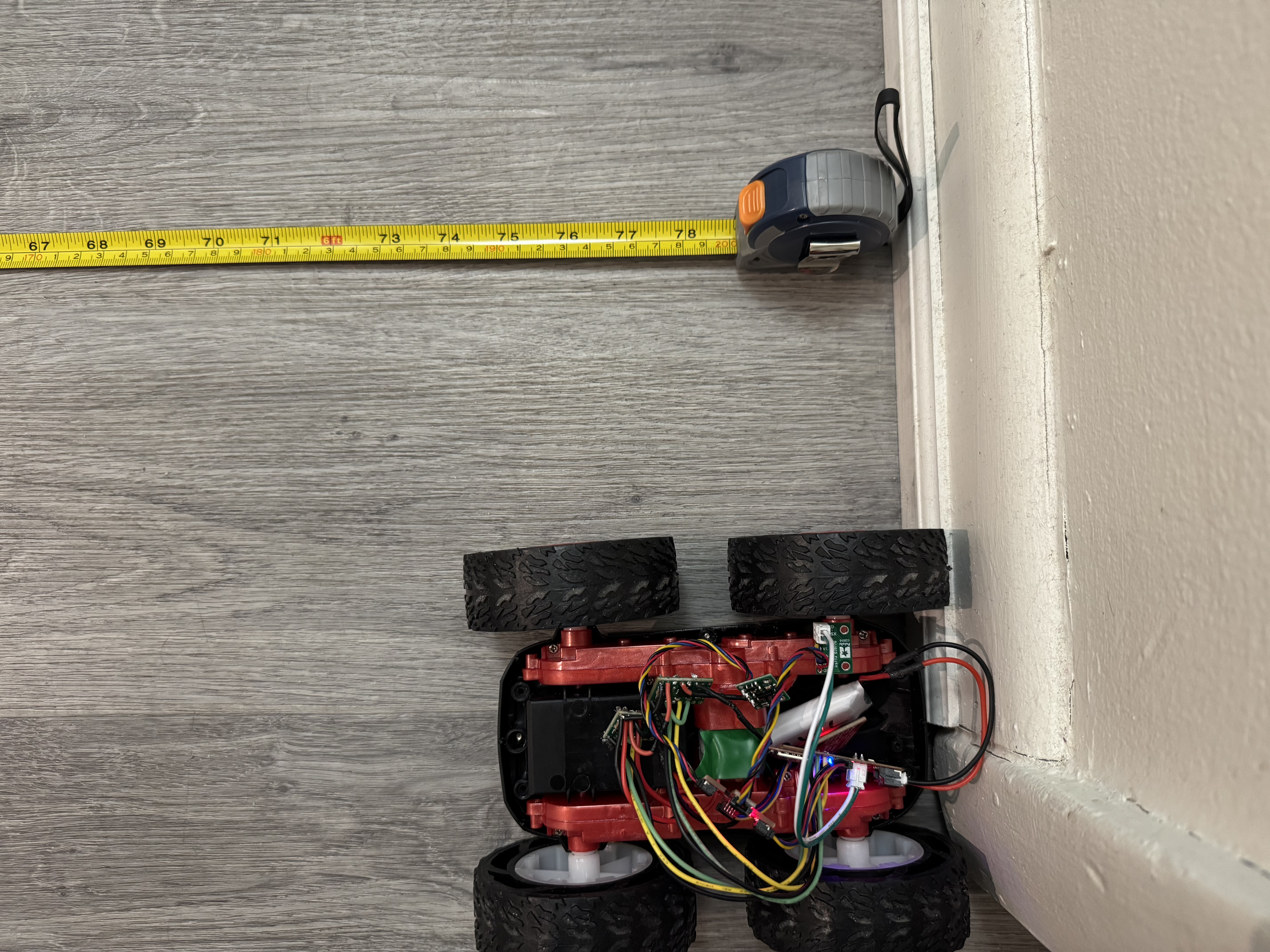
ble.send_command(CMD.SET_MOTOR_JOB, "30|30|1700")I then set a tape measure in my apartment to 2m and laid it on the floor. I placed my car next to it on one of the lines in my flooring, and would send a command from my computer with different speeds. I quickly realized that my left motor is weaker than my right one, but dialing the exact factor took many tries. A video of the calibration run is shown in Figure 9. I then updated my code to include this calibration factor if the two motor speeds are meant to be equal. I found that I needed to add 13.85% (35 PWM) to my left motor to make it drive in a straight line.
float calibration_factor = 13.85; //calculated experimentally

inline bool setBothMotors(float rightMotor, float leftMotor){
    if (rightMotor > 100 || rightMotor < -100) return false;
    if (leftMotor > 100 || leftMotor < -100) return false;

    if (rightMotor == leftMotor){ // Calibration to make it go straight
        leftMotor += calibration_factor;
    }

    bool rightReturn = setMotor(RIGHT, rightMotor);
    bool leftReturn = setMotor(LEFT, leftMotor);

    return rightReturn && leftReturn;
}

Open Loop Control
With the motors calibrated, I then had to do open loop control. The goal was to have the car move in a straight line, and then do some turns. To achieve this goal, I needed a way to easily change the speed while the car was in motion. To solve this problem, I added a ring buffer queue of motor inputs, so I could specify multiple commands with speeds and durations, and have them execute in order. I also added a command so I could send multiple commands at once
struct MotorJob {
  float right_percent;
  float left_percent;
  uint32_t duration_ms;
};

struct MotorJobQueue {
  static constexpr uint8_t CAP = 16; // pick size
  MotorJob buf[CAP];
  uint8_t head = 0;  // pop index
  uint8_t tail = 0;  // push index
  uint8_t count = 0;

  bool push(const MotorJob& j) {
    if (count >= CAP) return false;         // full
    buf[tail] = j;
    tail = (uint8_t)((tail + 1) % CAP);
    count++;
    return true;
  }

  bool pop(MotorJob& out) {
    if (count == 0) return false;           // empty
    out = buf[head];
    head = (uint8_t)((head + 1) % CAP);
    count--;
    return true;
  }

  void clear() { head = tail = count = 0; }
  bool empty() const { return count == 0; }
  bool full()  const { return count >= CAP; }
};

extern MotorJobQueue motor_q;

struct {
  bool active;
  uint32_t stop_at_ms;
  int16_t right_percent;
  int16_t left_percent;
} motor_job;static bool motor_queue_enabled = false;
MotorJobQueue motor_q;
void startMotorQueue() {
motor_queue_enabled = true;
}
void pauseMotorQueue() {
motor_queue_enabled = false;
}
bool startMotorJob(float right_percent, float left_percent, uint32_t duration_ms) {
// enqueue and let serviceMotorJob() start it
return queueMotorJob(right_percent, left_percent, duration_ms);
}
static void beginJob(const MotorJob& j) {
motor_job.active = true;
motor_job.right_percent = j.right_percent;
motor_job.left_percent = j.left_percent;
motor_job.stop_at_ms = millis() + j.duration_ms;
setBothMotors(j.right_percent, j.left_percent);
}
void serviceMotorJob() {
// If a job is running, always service its timeout (so it can stop)
if (motor_job.active) {
if ((int32_t)(millis() - motor_job.stop_at_ms) >= 0) {
motor_job.active = false;
stopBothMotors();
} else {
return; // still running
}
}
// If idle, only start next job if queue is enabled
if (!motor_queue_enabled) return;
// Try to start next job
MotorJob next;
if (motor_q.pop(next)) {
beginJob(next);
} else {
// Queue empty so auto-disable
motor_queue_enabled = false;
}
}
bool queueMotorJob(float right_percent, float left_percent, uint32_t duration_ms) {
MotorJob j{
right_percent,
left_percent,
duration_ms
};
return motor_q.push(j);
}
void abortMotorQueue(bool clear_pending) {
motor_queue_enabled = false;
motor_job.active = false;
stopBothMotors();
if (clear_pending) motor_q.clear();
}sequence = ["0|0|4000","43.85|30|2700", "30|-30|1300"] # turning sequence
sequence_string = "|".join(sequence)
#left, right, duration
ble.send_command(CMD.SET_MOTOR_SEQUENCE, sequence_string)
Additional 5000 Level Tasks
analogWrite() frequency
When measuring the PWM signals on the oscilloscope, the frequency was about 182 Hz. This is relatively low for driving DC motors with PWM. Because the motor windings have inductance, the current cannot change instantly and instead rises and falls during each PWM cycle. At low PWM frequencies like 182 Hz, the current has enough time to increase and decrease significantly, producing a waveform that can resemble a triangle wave rather than a nearly constant value. This results in larger torque ripple, which can cause audible noise and less smooth motor operation. Although the motors still run, using a higher PWM frequency would reduce the current ripple and improve smoothness. In future labs, it might be worth it to figure out how to increase the PWM frequency on the Artemis.
Lowest PWM value while moving
Using the ring buffer queue that I had implemented earlier, testing the minimum PWM signal that I could run the car at after it had started was easy. I first got the car moving, and quickly swapped to a lower PWM value and watched if the car would keep going or stop. For this test, I used a value of 30% for 700 ms to get the car moving. This was lower than my earlier measurements, but I performed the earlier measurements in a lab, and these ones in my apartment, so the floor could have made a difference. I also had the calibration added, so the left wheel was running faster. I found that after the car was moving, I could run it at 15% (38 PWM) and still have the car move. Setting it to 10% would cause the car to stop though.
sequence = ["0|0|4000","30|30|700", "15|15|3500"]

sequence_string = "|".join(sequence)

#left, right, duration
ble.send_command(CMD.SET_MOTOR_SEQUENCE, sequence_string)
Collaborations
This week I didn’t directly work with anyone, but I did reference Aidan Derocher’s previous write ups. I also used this StackOverflow discussion to help me with the PWM frequency: link