Lab 5: ToF PID Control
Objective
The purpose of this lab was to learn about PID controllers and use them with the ToF sensors to control the car.
Lab work
PreLab
For the prelab, I had to think about how to send data from the robot to the Python controller. Luckily for me, I had already set up all of this infrastructure in Lab 2. All I had to do to expand it was collect the motor information and send it. This is shown in the following code block.
snprintf(value_str, sizeof(value_str), "%lu:%.3f:%.3f:%.3f:%d:%d:%.3f:%.3f", time_data.values[i], imu_data.values[i].pitch, imu_data.values[i].roll, imu_data.values[i].yaw, dist_data.values[i].front, dist_data.values[i].side, motor_data.values[i].left_percent, motor_data.values[i].right_percent);One thing to note about my implementation is that I chose not to send the PID controller components. This was done because logging data took a very long time to transmit. I originally had a bug with my motor data where I sent a full float instead of %.3f, which made it take even longer. In the future, I am going to reduce the amount of data I send, since I mostly care about ToF data, yaw, and motor outputs.
Lab Tasks
PID
The first thing that I had to decide was what kind of controller to use. Because I am a 5000-level student, I had the choice of using a PI or a PID controller. I chose to use a PID controller because it would allow me to achieve a better response and (theoretically) no steady-state error. I say theoretically because I would need to tune it well in order to actually achieve those goals. I had also made a PID controller in a different class, so I just had to port the code over and modify it for this purpose. Because I knew we would need to use the controller for Lab 6 as well, I made a generic PID controller, so I can easily make more. I also added Python functions so that I could easily set the gains and setpoint via Bluetooth. The PID controller code is below.
struct PIDController {
   float kp, ki, kd;
   float setpoint;
   float integral;
   float windup_max;
   float prev_error;
   float prev_meas;
   float prev_deriv_filt;
   float alpha;
   uint32_t prev_time_ms;
   bool running;
   SensorReadFn readSensor; // plug in any sensor
};


float updatePID(PIDController& pid){
   if (!pid.running || pid.readSensor == nullptr) return 0.0f;

   uint32_t now = millis();
   float dt = (now - pid.prev_time_ms) / 1000.0f;
   if (dt <= 0.0f) return 0.0f;

   float measured = pid.readSensor();
   if (measured == -1){ //TODO this might not work for all sensor
       return 0.0f;
   }
   float error = measured - pid.setpoint;

   float derivative = pid.prev_deriv_filt;

   // Only update D on a fresh front measurement
   if (cur_dists.front_updated && cur_dists.front_dt > 0) {
       float real_measured = (float)cur_dists.front;
       float dt_real = cur_dists.front_dt / 1000.0f;

       float derivative_raw = -(real_measured - pid.prev_meas) / dt_real;
       derivative = pid.alpha * pid.prev_deriv_filt + (1.0f - pid.alpha) * derivative_raw;

       pid.prev_meas = real_measured;
       pid.prev_deriv_filt = derivative;
   }

   float p_term = pid.kp * error;
   float d_term = pid.kd * derivative;
   float i_term = pid.ki * pid.integral;

   float output = p_term + i_term + d_term;

   bool pos_sat = (output >= 40.0f && error > 0.0f);
   bool neg_sat = (output <= -40.0f && error < 0.0f);

   //Solving for windup. Only update the integral term if the output isnt saturated
   if(!(pos_sat || neg_sat)){
       pid.integral += error * dt;

       if(pid.integral >= pid.windup_max){
           pid.integral = pid.windup_max;
       } else if (pid.integral < -pid.windup_max){
           pid.integral = -pid.windup_max;
       }

       // Update i_term with new value
       i_term = pid.ki * pid.integral;
       output = p_term + i_term + d_term;
   }

   pid.prev_error = error;
   pid.prev_time_ms = now;
   pid.prev_meas = measured;
   pid.prev_deriv_filt = derivative;

   // Clamp output to motor range
   //TODO make this full range later, but start slow
   return constrain(output, -40.0f, 40.0f);
}
For my final values, I ended up with kp: 0.0126, ki: 0.025, and kd: 0.016. I also low-pass filtered my derivative term, using an alpha of 0.5. I parameterized the maximum value my integral could reach, setting windup_max to 40. In terms of the features that my controller implemented, I added both integration windup protection and derivative kick protection.
For the derivative kick, the specific code to implement the kick protection is:
float derivative_raw = -(real_measured - pid.prev_meas) / dt_real;This means that, rather than using the change in error for the value, it uses the change in measurement. This means that if the setpoint changes, the error would change dramatically, but the derivative term would not jump like the error.
As for the integration windup, the specific code is:
bool pos_sat = (output >= 40.0f && error > 0.0f);
bool neg_sat = (output <= -40.0f && error < 0.0f);


//Solving for windup. Only update the integral term if the output isnt saturated
if(!(pos_sat || neg_sat)){
    pid.integral += error * dt;

    if(pid.integral >= pid.windup_max){
        pid.integral = pid.windup_max;
    } else if (pid.integral < -pid.windup_max){
        pid.integral = -pid.windup_max;
    }

    // Update i_term with new value
    i_term = pid.ki * pid.integral;
    output = p_term + i_term + d_term;
}
Where windup_max is a value that I can set. One nice thing about my controller is that because I have functions to set the motors in terms of percentage both forward and backward, the output of the controller can be negative to move the car backwards. But for integration windup protection, I need to protect it in both directions, which is why it checks both positive and negative.
PID Frequency
One of the most important parts of the PID controller is getting it running fast. Having a slow controller will cause lots of problems, since it won’t be able to react well and the derivative and integral terms get weird due to a larger dt value. In Lab 4, I had made sure that my ToF sensors werent blocking the loop, which meant that the PID controller wasnt stuck waiting for them. Using the timestamps from my data collection, I determined that I had an average frequency of around 130 Hz. Something that I experimented with was putting the PID controller in an interrupt so that I could control the frequency myself. But when I tried it, I set the PID controller to 1 kHz, which starved the rest of Artemis because it was consuming a lot of CPU time. In the future, I might revisit the interrupt method, as I have used it on other microcontrollers, but they were also clocked much higher than the Artemis. Still, 130 Hz isn’t terrible (although faster would be better). And because the ToF sensors werent blocking the loop, I used long range mode. I did try using short range mode, but ran into problems with the controller not working great when the wall was beyond the ToF range. So for the sake of time, I went back to long range mode so the sensor was always in range. This did hurt the ToF update rate, which is unfortunate.
ToF Prediction
Because the ToF sensors updated very slowly (around 10 Hz from Lab 4), I had to add a linear extrapolation step for the sensors. The code is shown below:
Distances predictDistances(Distances &cur_dists, Distances &prev_dists){
Distances pred = cur_dists; //Fallback
float slope_front = (cur_dists.front - prev_dists.front) / (float)cur_dists.front_dt;
float delta_front = cur_dists.front - prev_dists.front;
if (abs(delta_front) < 5){
pred.front = cur_dists.front;
} else {
pred.front = (int)(cur_dists.front + slope_front * (float)(millis() - cur_dists.front_prev_time));
}
pred.front_updated = true;
float slope_side = (cur_dists.side - prev_dists.side) / (float)cur_dists.side_dt;
pred.side = (int)(cur_dists.side + slope_side * (float)(millis() - cur_dists.side_prev_time));
pred.side_updated = true;
return pred;
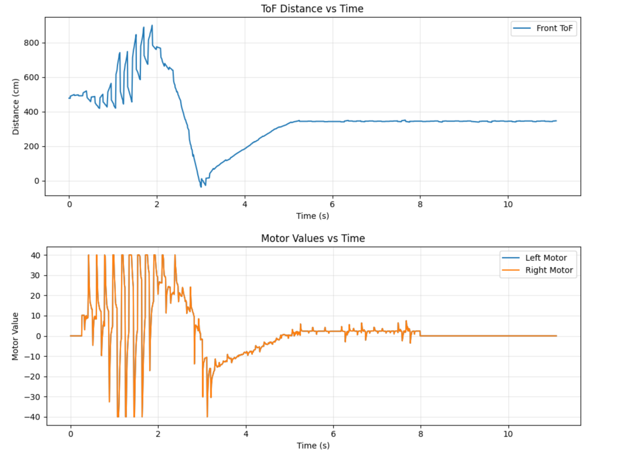
}This prediction somewhat helped, but it would also produce weird values as when the sensor was stationary, noise in the sensor would cause it to increase for a bit and then jump to the actual sensor reading. The start of Figure 1 shows these jumps from the predictor.
Results
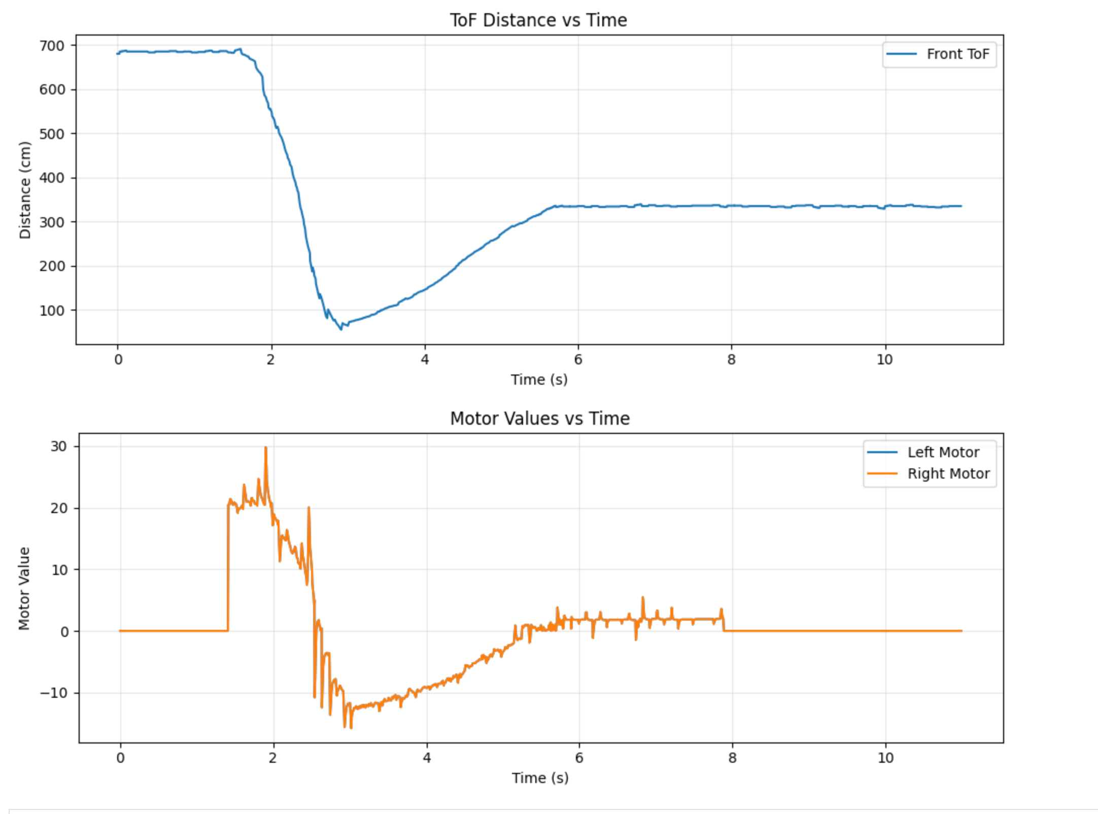
For the final output of the controller, I still think it needed a bit of tuning. It did work, but it overshot the wall a little bit, and the steady state error wasn’t perfectly 0. A lot of this comes down to the fact that controlling the car at slow speeds is hard, since the motors have a deadzone. I ended up needing to use active braking on the car to slow it down enough, and added some deadzone tweaks to improve its response. In the future, I might tweak my motor input system to automatically jump the values if they are too small. I also had a lot of trouble getting the ToF sensor to play nice, then updating so slowly, even with the prediction, really hurt the performance. The run is shown in the video below, and the ToF and motor data are in Figure 2.
I also tested to make sure that the robot tried to return to its setpoint if I disturbed it. Those results are shown in the video below.
5000 Level Tasks
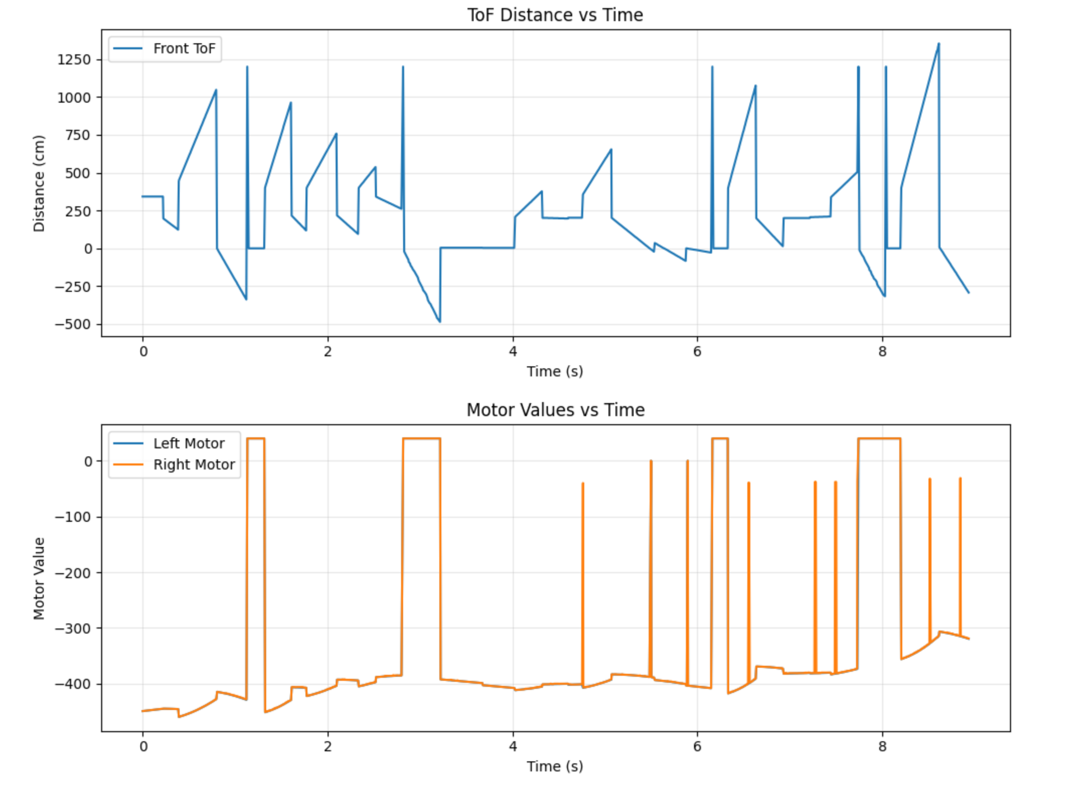
The 5000 level task was to implement the integrator windup protection which I briefly explained earlier. The reason for this protection is that if the setpoint changes suddenly (like me changing it mid-run), the integral term will change wildly. It also means that if you hold the car and it doesn’t have protection, the term will grow rapidly and cause the car to slam into the wall. Figure 3 shows the motor output with no windup protection. It reaches -400, which is not a valid control signal (it also shows a better graph of the prediction problem). And the video under it shows what the car is trying to do (I put it on a block so it didn’t slam into the wall)
Collaborations
This week, I discussed content with Immanuel Koshy. I didn’t use any previous years as reference.