Lab 6: IMU PID Control
Objective
The objective of this lab was to use PID with the IMU to control the angle of the car.
Lab work
PreLab
For this lab, I decided to modify what signals I was sending over Bluetooth. Before, I was sending pitch, roll, and yaw from the IMU. But for the purpose of this lab, pitch and roll aren’t relevant; only yaw is important. So I made a new command to send the time, yaw, ToF readings, and motor outputs. I did this because sending the data took 30-45 seconds each time due to the volume and how I was sending it. Now it is faster. I still didn’t log the PID values, mostly because of how much extra data they are. I also changed how I collected the data. Originally, I just sampled the data on every loop. The problem with this approach is that the time the data shows depends on the loop frequency, so a very fast loop means I don’t get much data over time and might miss important events. I set the data collection to a timer so it always samples for about 6 seconds.
// Collect IMU data
if(recording){

    // Record on a timer
    if ((millis() - prev_time) >= 4) { //Record 7.5 seconds of data
        //collectAllData(time_data, temp_data, imu_data, dist_data, motor_data); //TODO figure out how to transmit the sample rate more effectivly for PID control and TOF
        collectDriveData(time_data, yaw_data, dist_data, motor_data);
    }
}
Lab Tasks
DMP
Although I had previously gotten yaw working by integrating the gyroscope, for this lab I decided to use the IMU’s Digital Motion Processor (DMP). After running the demo code, I found it handled yaw drift significantly better than my integration setup, so I used it for the full controller. One important note is that I had to ensure the DMP didn’t block the loop while also ensuring it emptied its FIFO buffers fast enough. The code below shows how I set up and read from the DMP. Most of it comes from the DMP example.
// Call after the IMU is already initialized
bool initDMP(ICM_20948_I2C &imu){
  bool success = true; // Use success to show if the DMP configuration was successful

  // Initialize the DMP. initializeDMP is a weak function. You can overwrite it if you want to e.g. to change the sample rate
  success &= (imu.initializeDMP() == ICM_20948_Stat_Ok);

  // Enable the DMP Game Rotation Vector sensor
  success &= (imu.enableDMPSensor(INV_ICM20948_SENSOR_GAME_ROTATION_VECTOR) == ICM_20948_Stat_Ok);
  success &= (imu.setDMPODRrate(DMP_ODR_Reg_Quat6, 4) == ICM_20948_Stat_Ok); // Set to the maximum

  // Enable the FIFO
  success &= (imu.enableFIFO() == ICM_20948_Stat_Ok);

  // Enable the DMP
  success &= (imu.enableDMP() == ICM_20948_Stat_Ok);

  // Reset DMP
  success &= (imu.resetDMP() == ICM_20948_Stat_Ok);

  // Reset FIFO
  success &= (imu.resetFIFO() == ICM_20948_Stat_Ok);

  if(success){
    DEBUG_PRINTLN("DMP set up!");
  } else {
    DEBUG_PRINTLN("Failed to start the DMP");
  }
  return success;
}

void updateYaw(float *yaw, ICM_20948_I2C &sensor){
  icm_20948_DMP_data_t data;
  sensor.readDMPdataFromFIFO(&data);

  if ((sensor.status == ICM_20948_Stat_Ok) || (sensor.status == ICM_20948_Stat_FIFOMoreDataAvail)) // Was valid data available?
  {
    if ((data.header & DMP_header_bitmap_Quat6) > 0) // We have asked for GRV data so we should receive Quat6
    {
      // Scale to +/- 1
      float q1 = ((float)data.Quat6.Data.Q1) / 1073741824.0; // Convert to float. Divide by 2^30
      float q2 = ((float)data.Quat6.Data.Q2) / 1073741824.0; // Convert to float. Divide by 2^30
      float q3 = ((float)data.Quat6.Data.Q3) / 1073741824.0; // Convert to float. Divide by 2^30

      float q0 = sqrt(1.0 - ((q1 * q1) + (q2 * q2) + (q3 * q3)));

      float qw = q0; // See issue #145 - thank you @Gord1
      float qx = q2;
      float qy = q1;
      float qz = -q3;

      // yaw (z-axis rotation)
      float t3 = +2.0 * (qw * qz + qx * qy);
      float t4 = +1.0 - 2.0 * (qy * qy + qz * qz);
      *yaw = atan2(t3, t4) * 180.0 / PI;

      if (*yaw < 0.0f) {
        *yaw += 360.0f;
      }
    }
  }
}
PID
Because I am a 5000-level student and had already set up the PID infrastructure, I chose a full PID controller for this lab. Again, with proper tuning, this gives me a better response and minimal/ideally no, steady-state error. I was able to reuse the same code as in Lab 5, though I made some changes. I changed it to wrap the yaw value from ±180 degrees, even though it reports on the code as 0 to 360 degrees. I did this so that it would try to take the shortest path. For example, if it started at 355 degrees and I set the setpoint to 5, it could rotate towards 0 for a quick turn. But that only works if it doesn’t think that the error is 355-5. I also used PlatformIO build environments and build flags, so I didn’t have to delete any code for the ToF PID controller; I just had a flag for it. The code is shown below.
float updatePID(PIDController& pid){
    if (!pid.running || pid.readSensor == nullptr) return 0.0f;

    uint32_t now = millis();
    float dt = (now - pid.prev_time_ms) / 1000.0f;
    if (dt <= 0.0f) return 0.0f;

    float measured = pid.readSensor();
    if (measured == -1){ //TODO this might not work for all sensor
        return 0.0f;
    }

    #ifdef TOF
    float error = measured - pid.setpoint;
    #elif defined(IMU)
    float error = pid.setpoint - measured;
    if (error > 180.0f) error -= 360.0f;
    if (error < -180.0f) error += 360.0f;
    #endif


    #ifdef TOF
    float derivative = pid.prev_deriv_filt;

    // Only update D on a fresh front measurement
    if (cur_dists.front_updated && cur_dists.front_dt > 0) {
        float real_measured = (float)cur_dists.front;
        float dt_real = cur_dists.front_dt / 1000.0f;

        float derivative_raw = -(real_measured - pid.prev_meas) / dt_real;
        derivative = pid.alpha * pid.prev_deriv_filt + (1.0f - pid.alpha) * derivative_raw;

        pid.prev_meas = real_measured;
        pid.prev_deriv_filt = derivative;
    }
    #elif defined(IMU)
    float delta_meas = measured - pid.prev_meas;
    if (delta_meas > 180.0f) delta_meas -= 360.0f;
    if (delta_meas < -180.0f) delta_meas += 360.0f;

    float derivative_raw = -delta_meas / dt;
    float derivative = pid.alpha * pid.prev_deriv_filt + (1.0f - pid.alpha) * derivative_raw;
    #endif

    // float derivative_raw = -(measured - pid.prev_meas) / dt; // Calculated this way to eliminate derivative kick

    // float derivative = pid.alpha * pid.prev_deriv_filt + (1 - pid.alpha) * derivative_raw;

    float p_term = pid.kp * error;
    float d_term = pid.kd * derivative;
    float i_term = pid.ki * pid.integral;

    float output = p_term + i_term + d_term;

    bool pos_sat = (output >= 40.0f && error > 0.0f);
    bool neg_sat = (output <= -40.0f && error < 0.0f);

    //Solving for windup. Only update the integral term if the output isnt saturated
    if(!(pos_sat || neg_sat)){
        pid.integral += error * dt;

        if(pid.integral >= pid.windup_max){
            pid.integral = pid.windup_max;
        } else if (pid.integral < -pid.windup_max){
            pid.integral = -pid.windup_max;
        }

        // Update i_term with new value
        i_term = pid.ki * pid.integral;
        output = p_term + i_term + d_term;
    }

    pid.prev_error = error;
    pid.prev_time_ms = now;
    pid.prev_meas = measured;
    pid.prev_deriv_filt = derivative;


    // Clamp output to motor range
    //TODO make this full range later, but start slow
    output = constrain(output, -60.0f, 60.0f);
    #ifdef DEBUG_ENABLED
    DEBUG_PRINTF("p: %.3f, i: %.3f, d: %.3f, out: %.3f\n", p_term, i_term, d_term, output);
    #endif
    return output;
}
PID Frequency
The PID controller runs a bit faster in this lab compared to Lab 5. I measured a frequency of 220 Hz. This speedup is because I wasn’t running the full ToF sensor code since I only cared about the IMU, and the prediction steps are somewhat heavy. I didn’t get it working with an interrupt, though, which is still something I am interested in trying.
Results
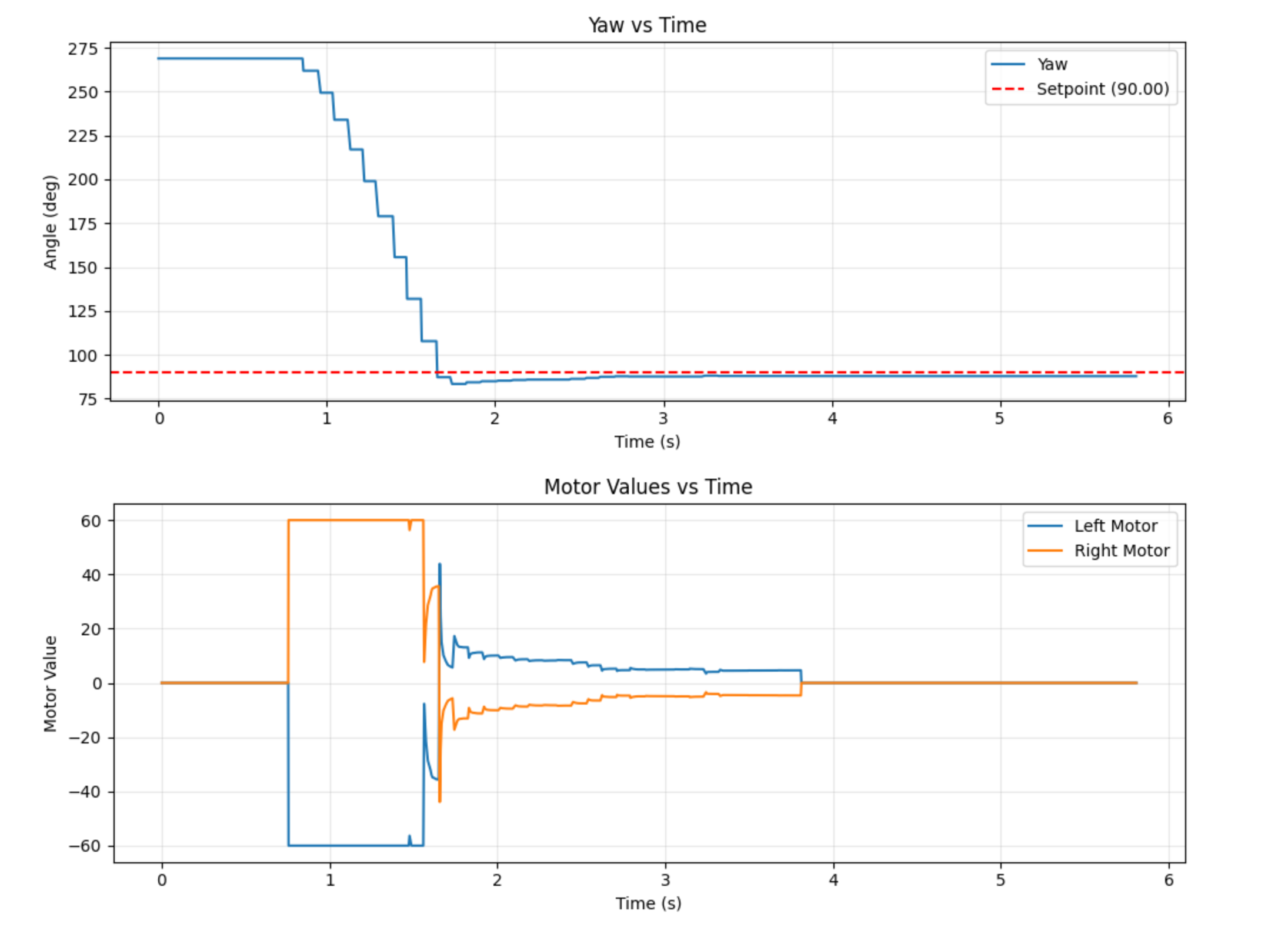
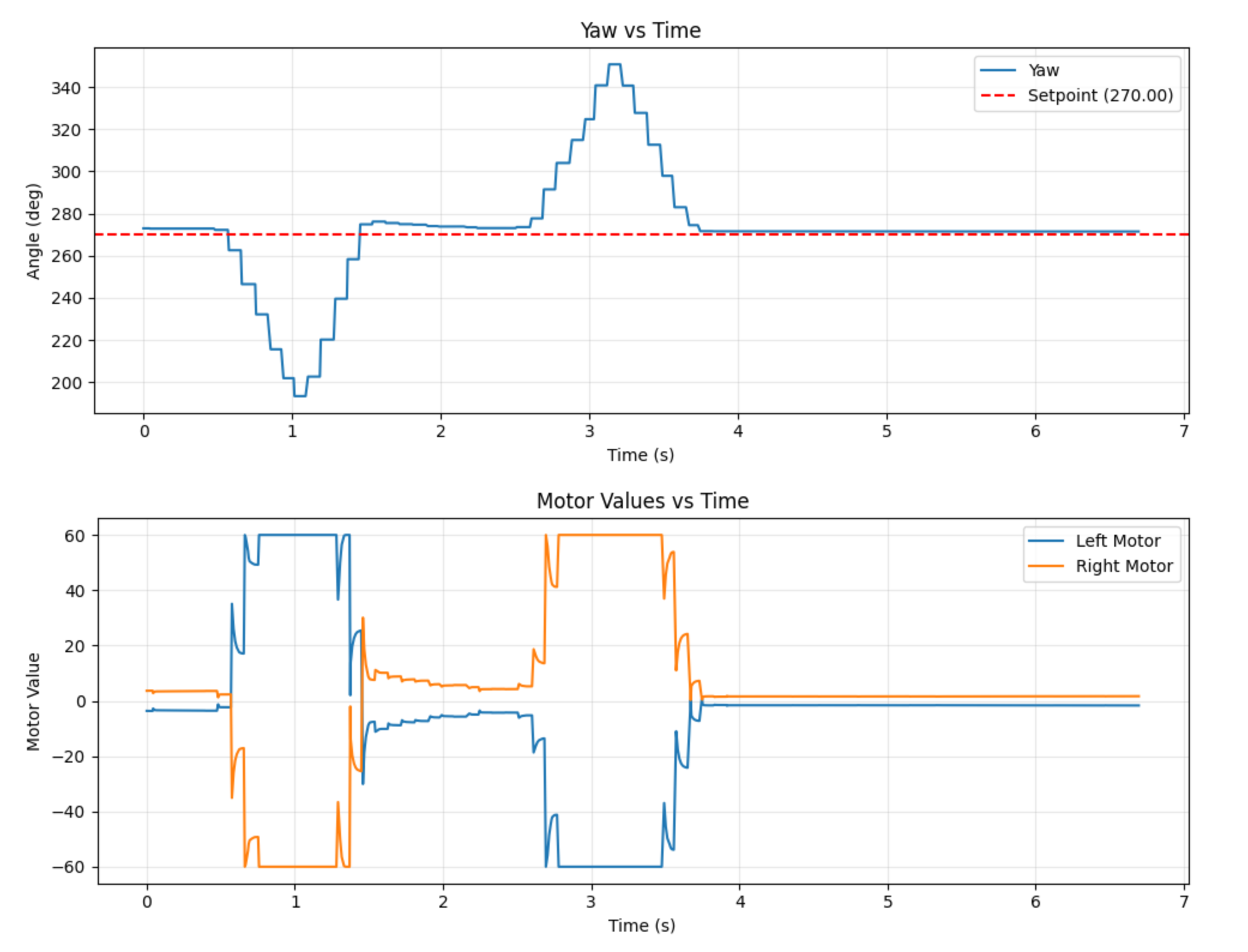
I found tuning the PID controller much easier for this lab than for Lab 5. I think some of it is that the IMU is easier to work with. But I was also able to get much better final results. I found that the values that worked for me were kp: 2.0, ki: 0.09, kd: 0.03, alpha: 0.5, windup_max: 30. In Lab 5, I was clamping the motor speeds to ±40% to make sure that they didn’t go too fast. For this lab, I found that I needed to increase the max speed and minimum speeds because starting the car with the wheels spinning in opposite directions required more force to overcome friction. I also tested to ensure that the controller would try to return the car to its setpoint, as seen at the end of the video. Figure 1 shows the normal results, and Figure 2 shows the graph when I disturbed the robot. The results in figure 1 look very good. There is a very small overshoot, and the robot basically hits its target.
5000 Level Tasks
I was able to use the same windup protection as Lab 5. The windup behavior would be exactly the same as in Lab 5, just the robot would spin uncontrollably in a circle since the wheels are spinning in different directions. I fixed it by both capping the integration term and the overall PID controller output. The video below shows integrator windup.
bool pos_sat = (output >= 40.0f && error > 0.0f);
    bool neg_sat = (output <= -40.0f && error < 0.0f);

    //Solving for windup. Only update the integral term if the output isnt saturated
    if(!(pos_sat || neg_sat)){
        pid.integral += error * dt;

        if(pid.integral >= pid.windup_max){
            pid.integral = pid.windup_max;
        } else if (pid.integral < -pid.windup_max){
            pid.integral = -pid.windup_max;
        }

        // Update i_term with new value
        i_term = pid.ki * pid.integral;
        output = p_term + i_term + d_term;
    }
Collaborations
I talked with Immanuel Koshy about the content of this lab. I didn’t use any previous students’ work as a guide, but I did use the lab instructions for the DMP unit.